2
INSTALLATION GUIDE
MODEL AC INPUT VEHICLE INPUT SOLAR INPUT BA
TTER
Y OUTPUT
BMS1230S3
230V
, 50-60Hz,
560W
9 - 32VDC,
520W
9 - 32VDC,
520W
12VDC Nom./ 0-30A
Please r
efer to o
wners
manual for appropriate wir
e
gauge and fuse r
atings.
The Redar
c CAN system is
designed to oper
ate Redar
c
CAN based devices only
.
W
ARNING:
Befor
e obtaining access to ter
minals,
all supply cir
cuits must be disconnected
30
AMPS
LITHIUM PROFILE
PROFILE
Li
Fe
P
O
4
Solar
Panel
50A Fuse
Not
supplied
Start
Ba
tter
y
Essential Loads*2
Display
BMS1230S3
+
+
+
Mains AC
from
mains po
wer
(rear side)
AC
MAINS
-
+
Non-essential
Loads*2
House
Ba
tter
y
1
2
3
4
5
6
Ba
tter
y
Sensor
40A Fuse
Not
supplied
Load
Fuses
Not
supplied
*1
Ignition
Trigger
SBI12-BLD
*1
The size of this fuse r
elates to
the total curr
ent dr
aw of all the
loads connected to the House
Batter
y, and should be r
ated
slightly higher than this. REDARC
recommend the use of MIDI
Style Fuses.
*2 Essential loads ar
e loads whic
h
must be left on at all times,
until
the batter
y is flat. Non-essential
loads ar
e those switc
hed off
when the batter
y r
eac
hes a
particular lo
w-c
har
ge
level,whic
h can be set in the
‘Adv
anced Settings’ menu.
*3 Both CANBus connections can
be used for either the Display or
Batter
y Sensor
*4 Ensur
e the RED ter
minal on the
Batter
y Sensor is connected to
the Batter
y Positive
Ter
minal.
Typical Setup
*3
*3
*4
A single fuse and holder
setup from the Fuse Kits
available from REDARC.
Part number FK40 (40A)
or FK60 (60A).
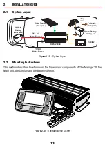
Figure 2.4.4.2
-
Typical setup.
20

