background image

Redback® Proudly Made In Australia

6

The cursor is now positioned over the hour section of the start time as shown in Fig 3.9. 

Press the UP and DOWN

buttons to change the 

hour/min/secs.

Enter

Press the ENTER

button to make your

selection

Menu

Press the MENU

button to exit at any 

time.

1)      Monday           

 Start @ 23:00:00

1)        Monday           

 Start @ 00:00:00

1)    

Monday 

 Start @ 01:00:00

1)       Monday 

 Start @ 02:00:00

1)    

Monday           

 Start @ 22:00:00

Start time

1)        Monday           

 Start @ 00:00:00

Press the +10 button to 

scroll up 10 

hours/min/secs

+10

Fig 3.9

Change the hour by pressing the +10, up and down 
buttons and press “Enter” when finished. The cursor 
will now move to the minute section of the start time. 
Repeat the above procedure to change the minutes 
and press “Enter” when finished. The cursor will now 
move to the seconds section of the start time. Repeat 
the above procedure again to change the seconds and 
press “Enter” when finished. The start time is now set 
for this Station (or Event).
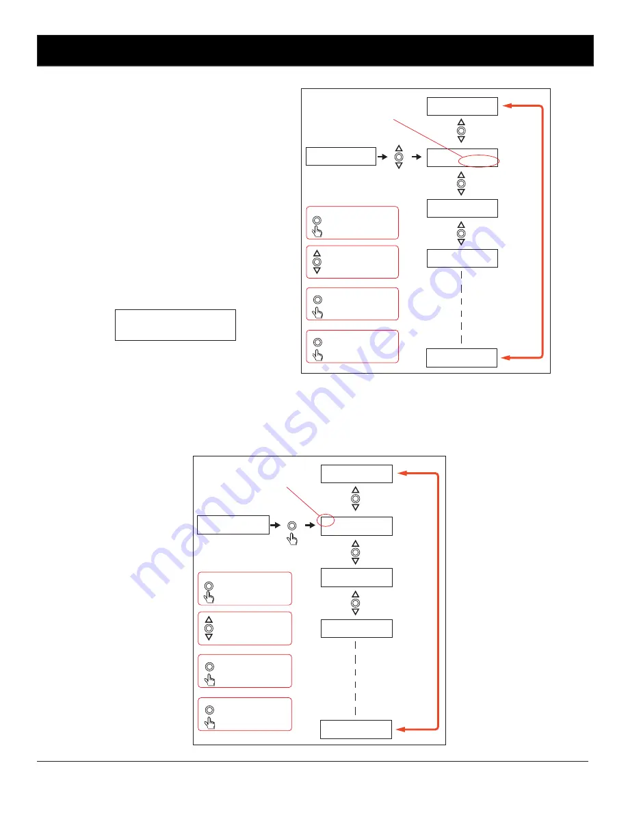
After completing the start time, the screen will change 
to the Zone and Duration options screen as shown in 
Fig 3.10.

Fig 3.10

1) ZONE  DURATION           

   OFF   00:00:00

From this point the user can scroll through all 50 stations using the up and down buttons as shown in fig 3.11. This makes 
it very easy to view all Output Zone settings at a glance. Once the station number desired is shown on the LCD press the 
“Enter” button to confirm and move to the next step which is to make changes to the zone output.

Fig 3.11

Enter

Press the UP and DOWN

buttons to scroll up and 

down.

Enter

Press the ENTER

button to make your

selection

Menu

Press the MENU

button to exit at any 

time.

Station (or Event) number

Press the +10 button to 

scroll up 10 stations

+10

1) ZONE  DURATION           

   OFF   00:00:00

1) ZONE  DURATION           

   OFF   00:00:00

2) ZONE  DURATION           

   OFF   00:00:00

3) ZONE  DURATION           

   OFF   00:00:00

49) ZONE DURATION           

   OFF   00:00:00

50) ZONE DURATION           

   OFF   00:00:00

Summary of Contents for A 1708

Page 1: ...tput 24 Hour 7 day Timer Redback Proudly Made In Australia IMPORTANT NOTE Please read these instructions carefully from front to back prior to installation They include important setup instructions Fa...

Page 2: ...ill become active and 24V DC will be present at the terminals At the same time the closing contact for that zone will short and stay that way until the zone is again set OFF NOTE the 24V DC outputs sw...

Page 3: ...Manual Select of Output Zones Screen This is the first of 5 sub menu screens which are navigated by pressing the up and down buttons as shown in Fig 3 3 Pressing the Menu button again will return the...

Page 4: ...a Station Time Sub Menu as shown in Fig 3 3 If this is the first time entering this menu the screen should appear as shown in Fig 3 6 The number 1 shown is the Station or Event number which is highli...

Page 5: ...the day of the week that the Event will take place and can be any day from Monday to Sunday or one of many multiple day options which are listed below Pressing the up and down buttons will scroll thr...

Page 6: ...ure again to change the seconds and press Enter when finished The start time is now set for this Station or Event After completing the start time the screen will change to the Zone and Duration option...

Page 7: ...our by pressing the 10 up and down buttons and press Enter when finished The cursor will now move to the minute section of the duration Repeat the above procedure to change the minutes and press Enter...

Page 8: ...0 Edit Press the 10 button to change the hour min secs 10 Press the UP and DOWN buttons to change the day Enter Press the ENTER button to make your selection Menu Press the MENU button to exit at any...

Page 9: ...hed off when adjusting DIP switches New settings will be effective when power is switched back on 4 0 DIP SWITCH SETTINGS There are four DIP switches accessible on the rear of the A 1708 which are for...

Page 10: ...r Memory Mode will be restricted Therefore there can be no erasing of the Station Event times stored in memory 6 0 REAR CONNECTIONS 6 1 24V DC Connectors DC sockets have been provided for 24V DC input...

Page 11: ...closing contact of the timer is connected to the Input 1 trigger of the message player When Zone 2 is activated by the timer message 1 of the message player will be played 4 L R Line Out 12 30V DC Sw...

Page 12: ...ME 1 2 3 4 5 6 7 8 9 10 11 12 13 14 15 16 17 18 19 20 21 22 23 24 25 26 27 28 29 30 31 32 33 34 35 36 37 38 39 40 41 42 43 44 45 46 47 48 49 50 OUTPUT 1 OUTPUT 2 OUTPUT 3 OUTPUT 4 7 0 EVENT TIMES RECO...

Reviews: