background image

www.redbackaudio.com.au

Redback® Proudly Made In Australia

7

Redback® A 4270/80

 Four Zone Paging PA Amplifier

9.0 REMOTE VOLUME (Optional)

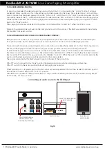
It is possible to control the master volume with the addition of the A 4373 Digital Remote volume board and a 1k

Ω


potentiometer (or Altronics A 2280B wall plate) fitted across the terminals labelled “Optional Plugin” on the rear of the 
amplifier. The plugin board is fitted inside the amplifier in the location shown in figure 4.

NOTE: Take special care with the orientation of the board and remove power from the amplifier before fitting.

Fig 4

Fig 5

PHANTOM POWER 

DIP SWITCHES

1=MIC1

2=MIC2

3=MIC3

VOX1

VOX2

ON
OFF

ON
OFF

EARTH

LIFT 

SWITCH

EARTH

LIFT

PL

UGIN

PL

UGIN

i

Wiring speakers in parallel for 70/100V line:  

Where several speakers are to

be used at one time, on one circuit, it becomes necessary to use speakers fitted

with line-matching transformers.  This is to overcome the effects of connecting

speakers in parallel and cable losses. The amplifier generally has an output

voltage of 100 volts (70 volts is typically used in North America, however

operation is similar). In this configuration the total wattage load on the amplifier

is derived from adding all the line transformer primary tap ratings together.  For

example, 70 one watt speakers will have a total speaker load of 70 watts.  Or

alternatively, it is conceivable to connect 100 one watt speakers to a 100 watt,

100 volt line amplifier.

Measuring 70/100V Line Speaker Impedance:  

To measure amplifier system

load, you must use an impedance meter in order to measure the ac resistance

of the connected speaker network. Impedance cannot be measured with a

standard multimeter, as this measures the dc resistance. Use the Altronics

Q 2003 or similar impedance meter.

About 70V & 100V Line Speaker Systems

Load        70V             100V

0.5W        9.4kΩ          20k Ω

0.66W      7.12kΩ        15k Ω

1W           4.7kΩ          10k Ω

1.25W      3.76kΩ        8k Ω

2W           2.35kΩ        5k Ω

2.5W        1.88kΩ        4k Ω

3W           1.56kΩ        3.3k Ω

5W           940Ω           2k Ω

7.5W        626Ω           1.3k Ω

10W         470Ω           1k Ω

15W         313Ω           666 Ω

20W         235Ω           500 Ω

30W         156Ω           333 Ω

40W         117Ω           250 Ω

60W         78Ω             166 Ω

100W       47Ω             100 Ω

125W       37Ω             80 Ω

250W       19Ω             40 Ω

500W       9.4Ω            20 Ω

Summary of Contents for A 4270

Page 1: ...se read these instructions carefully from front to back prior to installation They include important setup instructions Failure to follow these instructions may prevent the unit from working as design...

Page 2: ...users reliable products of high build quality with local product support We believe there is significant added value for customers when purchasing an Australian made Redback amplifier or PA product Lo...

Page 3: ...Thermal overload overcurrent and overload protection circuitry and fuses on both AC and DC provide excellent fault condition protection and robust performance The amplifier also utilises a half power...

Page 4: ...tes when the input signal is clipping 11 OverLoad Indicator This LED indicates when the output is drawing too much current from the amplifier The output will be disconnected until the current draw is...

Page 5: ...ore details 7 Inputs 1 3 These inputs can be either a balanced XLR input with sensitivities of 500mV or dual RCA line inputs with a 1V input sensitivity The line input dual RCA connectors are internal...

Page 6: ...one inputs have DIP switch selectable phantom power When enabled 15V DC will be connected to the Hot and Cold pins of the corresponding XLR To access the DIP switches first disconnect power from the u...

Page 7: ...of connecting speakers in parallel and cable losses The amplifier generally has an output voltage of 100 volts 70 volts is typically used in North America however operation is similar In this configu...

Page 8: ...ging consoles can be connected as shown The paging consoles provide paging to all four output zones and will override the background music to those zones refer to section 13 0 for more details Fig 6 R...

Page 9: ...from the amplifier 2 RJ45 connector For connection back to the A 4270 or A 4280 Either port can be used 3 DIP switch options These switches set the pre announcement chime and set the ID number 4 BGM B...

Page 10: ...o the 3 5mm input jack on the rear of the paging microphone as shown in Figure 10 This provides a local source of background music To activate the background music first make sure the Push to Talk PTT...

Page 11: ...hown in figure 11 The messages have to be recordered in MP3 format using any readily available PC software or other means and then transferred to these folders Activating the Voice Over Message Voice...

Page 12: ...ts of the SD Card include a Library folder of sample MP3 files and five folders for the MP3 files associated with the various triggers There should be default MP3 files included in each folder These w...

Page 13: ...e MP3 file NOTE the new MP3 file cannot be Read only To check this right click on the MP3 file and scroll down and select Properties you will get a window that looks like figure 15 Make sure the Read...

Page 14: ...lifier and insert it into your PC Follow the steps on page 11 to open the SD card 3 Extract the contents of the Zip file to the root folder of the SD Card 4 Rename the extracted BIN file to update BIN...

Page 15: ...Pin XLR OUTPUT CONNECTORS Speakers Screw terminals INPUT CONNECTORS Inputs 3 pin XLR balanced or 2 x RCA 24V DC power Screw terminals 240V AC power IEC power connector MUTING PTT via microphone switc...

Page 16: ...r Amplifier The Redback A 4395A is a 500 Watt Mixer amplifier for installations requiring a high power zone amplifier The amplifier has two audio inputs with input 1 either a balanced XLR input or dua...

Reviews: