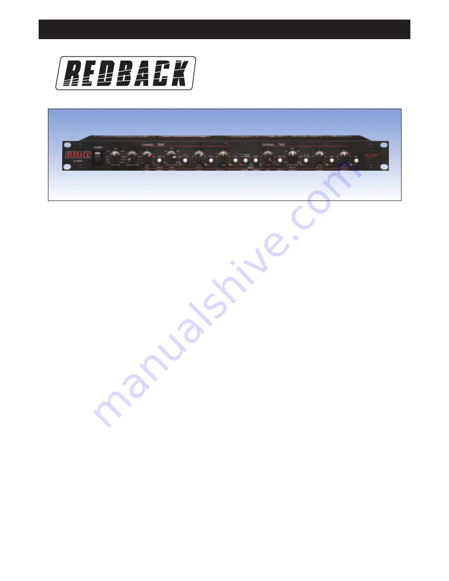
A 5350 2 Way Stereo / 3 Way Mono Active Crossover
®
www.altronics.com.au
Operating Instructions
STEREO 2-WAY MODE
In 2-way stereo mode the controls are marked BELOW the horizontal red line.
Channel one and channel two functions are identical in the stereo mode.
LEDs are disabled for controls which are non-functional in this mode.
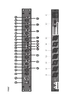
See panel diagrams.
4
&
21
INPUT GAIN Controls the INPUT level with +/- 12 dB of gain.
6
&
23
LOW CUT Switch for selecting the 40 Hz high pass filter.
5
&
22
LED indicating low cut mode operation.
7
&
24
LOW/HIGH Selects crossover point between LOW and HIGH outputs.
8, 9, 25, 26
X10 LED Indicates and changes the LOW/HIGH crossover fre-
quency range is 450 Hz to 9.6 kHz.
10
&
27
LOW OUTPUT Controls low frequency output with a range 0 to 10.
12
&
29
PHASE INVERT Switch for reversing polarity on the low output.
11
&
28
LED indicates that the phase is reversed.
13
&
30
HIGH OUTPUT Controls high frequency output with a range 0 to 10.
15
&
32
PHASE INVERT Switch for reversing the polarity on the High Output.
14
&
31
LED indicates that the phase is reversed.
20
STEREO LED indicating stereo mode operation.
MONO 3 -WAY MODE
In 3-way mono operation the controls are marked ABOVE the horizontal blue
line. Front panel controls not described in this section are not active in mono
3-way mode. LEDs are disabled for controls which are nonfunctional in this
mode.
See panel diagrams.
1
Power Switch Press this switch to turn the power ON. Press it again to turn
the power OFF.
2
Sub woofer frequency controls Selects crossover point in low frequency.
3
Sub woofer output level controls Controls the sub woofer output level.
4
INPUT GAIN Controls the input level with +/- 12 dB of gain.
6
LOW CUT Switch for selecting the 40 Hz high pass filter.
5
LED indicates that the phase is reversed.
7
LOW/MID Selects crossover point between LOW and MID frequencies.
8
&
9
X10 LED Indicates And Change the LOW/MID crossover range is 450
Hz to 9.6 kHz.
24
MID/HIGH Selects crossover point between MID and HIGH frequencies.
25
&
26
X10 LED Indicates And Change the MID/HIGH crossover frequency
range is 450 Hz to 9.6 kHz
10
LOW OUTPUT Controls LOW frequency output level with a range 0 to 10.
12
PHASE INVERT Switch for reversing the polarity on the Low Output.
11
LED indicates that the phase is reversed.
27
MID OUTPUT Controls MID frequency output with a range of 0 to 10.
29
PHASE INVERT Switch for reversing the polarity on the mid output.
28
LED indicates that the phase is reversed.
30
HIGH OUTPUT Controls HIGH frequency output with a range of 0 to 10.
32
PHASE INVERT Switch for reversing the polarity on the high output.
31
LED indicates that the phase is reversed.
35
&
38
Input jack. For connecting to pre amplifiers or mixer output.
33
&
36
High frequency output jack. For connecting to power amplifiers.
34
Low frequency output jack. For connecting to power amplifiers.
40
Voltage selector switch The switch for selection 110v or 220v.
41
AC input. The AC socket is for connecting to power source.
18
MONO LED indicating mono mode operation.
19
The mode switches on the front panel of the unit are used to select one
of two modes of operation in the A 5350. There could be disastrous conse-
quences if the crossover were improperly setup or the switches were mistak-
enly pushed during the regular operation of a sound system. Therefore great
care should be taken when setting these switches. There is a mode diagram
on the back panel to help you understand at a glance how this is done.
The following steps should be taken in setting up your system:
• Know the loudspeaker manufacturer’s requirements regarding the amplifi-
cation needs of your particular speaker system. Follow the manufacturer’s
guidelines carefully, as Altronics is not responsible for damage relating to
improper setup or implementation of the A 5350.
• Without any audio or power connections in place, use the switches on the
crossover to set it to the proper mode of operation; either stereo 2-way or
mono 3-way for the A 5350.
• Use the literature that came with your speaker system to properly set up
the mode of operation and crossover frequencies to the manufacturer‘s
specifications.
For stereo 2-way operation use the markings above the connectors. To oper-
ate the A 5350 in mono 3-way mode use the markings below the connectors.
The connectors which are not used in the selected mode are marked “not
used”. This designation applies only to that mode of operation.
AUDIO CONNECTIONS
• Before connecting anything to the crossover, make sure it is not connected
to any power source.
• Be sure that the source device (equalizer, compressor, mixing console,
etc.) for the A 5350 is turned off. Connect the output(s) of the source
device to the inputs of the crossover, following the rear panel markings
carefully.


