background image


3.


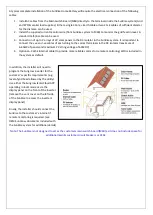
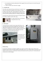
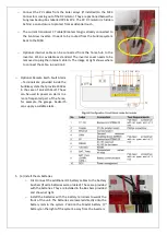
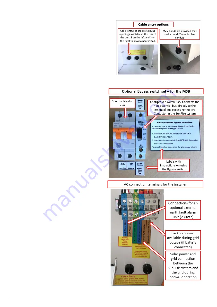
Cable entry options: Pass all cables into and out of 

the unit through the M25 penetrations that are 

provided in the rear of the enclosure. The cable 

glands provided in the Parts Kit allow standard 

flexible conduit to be connected while maintaining 

the IP rating of the enclosure. (Note: penetrations 

can be made elsewhere in the enclosure, if more 

appropriate) Use the provided cable glands or other 

suitable glands to maintain the IP rating of the 

system. 


4.


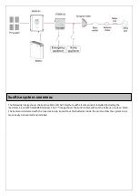
Connect the external cables;  

o


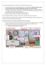
Decide if the optional wiring for the back-up 

feature is required. If it is then in the MSB split 

the loads into Essential and Non-essential: 

This allows the Back-up feature to be used to 

support selected essential loads during a 

blackout. A maximum of 3kVA can be supplied 

during back-up operation  (5kVA during the 

day, if PV is connected directly to the SunRise 

system), however it is recommended to 

connect far lower loads to the essential circuit 

as the amount of energy available is limited to 

the battery capacity (and the solar 

contribution during the daytime) – The Parts 

Kit contains a 25A 2-pole MCB to isolate the 

Inverter (Grid/Solar) and Essential/EPS 

circuits. In addition, a 63A Changeover switch 

is included. This is a By-pass switch that 

directly connects the Essential loads to the 

Non-essential loads. It is only used if the 

SunRise system is not operating, or not yet 

installed.  Labels are also included to use in 

the MSB. 

o


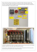
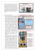
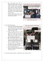
Connect the  AC cables of the Grid and 

Essential supplies from the Main Switch 

Board (MSB) directly to the terminals inside 

the SunRise system (Grid/Solar  and 

EPS/Essential load supplies). A single 3-Core + 

Earth cable of sufficient diamter for the 

distance  can be used  (RedEarth can supply 

this cable). Otherwise two 2C+E cables can be 

used.  In this case the two earths and neutrals 

are connected to the Grid/Solar Earth and 

Neutral terminals. Note that the essential 

circuits are permanently supplied via the 

transfer switch inside the SunRise system. 

This means that twice the distance from the 

MSB to the SunRise needs to used to 

determine the cable size for the Essential load circuits. 

Summary of Contents for SunRise 1-PH

Page 1: ...SunRise Home Battery System Model SGS 1 PH AUTO with LG BYD battery Installation Manual...

Page 2: ...16 5kWh Each battery weighs 24kg Dimensions 104 cm H x 97 cm W x 54 cm D Safety Instructions Physical Specifications WARNING Installation and Maintenance of the Sunrise System should only be done by a...

Page 3: ...old loads fridges lights etc can be powered during a power outage This uses an automatic transfer switch included inside the SunRise unit When installed without batteries excess PV generated during th...

Page 4: ...imum of 6 65kW of panels and maximum PV string voltage of 600VDC 4 Optional Cat5E internet cable to provide more reliable comms for remote monitoring WiFi is included in the system as default In addit...

Page 5: ...ing the maximum 5 x 6 5kWh LG M48 batteries The 2nd image shows the SunRise SGS without the batteries in place Note The Sunrise is delivered with the inverter inside but without the batteries inside t...

Page 6: ......

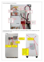
Page 7: ...The internal wiring layout is shown below The right side of the SunRise system includes the AC and DC Switch assemblies the left side allows access to the control panel of the inverter...

Page 8: ...their solar inverters and removes the requirement to add AC and DC Isolators on the wall next to the system The system is supplied without the batteries installed This allows the enclosure to be more...

Page 9: ...er induction including system monitoring using the Sungrow app on their phone if possible Apply appropriate labels in on MSB see included SunRise Signage Overview document Complete a commissioning rep...

Page 10: ...f 5 x 3 3 kWh batteries Other battery options can be ordered including BYD and Troppo batteries 3 1 x Parts Kit containing all parts to complete the installation of the SunRise battery system in a nor...

Page 11: ...from the top 2 Wall mount The system can also be wall mounted using standard heavy duty airconditioning mounting bracket available from RedEarth These images show a SunRise system installed on a wall...

Page 12: ...LG battery cables KEEP SAME LENGTH AS SUPPLIED BY Redearthng up the FPA3 The diagram below shows an overview of the electrical connection inside the SunRise System STEP 4 Wiring up the Sunrise...

Page 13: ...cables to the PV isolator inside the SunRise 4 Optional Cat5E internet cable to the SunRise otherwise use Wi Fi Note All isolators and MCBs are included in the Sunrise so no wall mounted isolators are...

Page 14: ...f energy available is limited to the battery capacity and the solar contribution during the daytime The Parts Kit contains a 25A 2 pole MCB to isolate the Inverter Grid Solar and Essential EPS circuit...

Page 15: ...at right shows where to connect the cable in position 3 o Optional Remote Earth Fault Alarm Terminals are provided inside the SunRise system that provide 230Vac in the case of an Earth Fault These can...

Page 16: ...ries They are installed in the Bus bars provided and shown at right b Install the batteries with the battery terminals towards the front of the unit The batteries are lowered directly onto the battery...

Page 17: ...he battery terminal connections are correct if batteries are included in the system Start up the battery in the SunRise system if batteries are included otherwise skip this section LG Battery 1 Once c...

Page 18: ...attery has completed start up which takes 1 minute the indicators as shown below will be on For LG battery Trouble shooting refer to pp31 of the LG Installation manual which has been included with you...

Page 19: ......

Page 20: ...itself if you do not want to connect via your phone and Local Mode To access the control panel remove the vent on the left side of the system as shown here o Work through the settings on the SunGrow...

Page 21: ...e ordered from RedEarth together with the required communication and battery cables The procedure to add extra battery modules is outlined below The LG battery must be shut down to add modules Note th...

Page 22: ......
Page 23: ...gency Power Supply AC POWER EPS rated Power from battery only 3000VA EPS rated Power with PV support 5000VA Changeover time to EPS when outage occurs 3 sec Max Charging current 65A Max Discharging cur...

Page 24: ...l Voltage 51 2 Vdc Lithium ion chemistry LiFePO4 OPERATING CONDITIONS Operating voltage 40 56 4 Vdc Max float voltage 57 4 Vdc Available operating temperature C 10 50 C Certification UL1642 IEC62619 S...

Page 25: ...ons Miscellaneous spare parts o HD Air con bracket set with additional bolts o 4 core cable 3C E in 10mm2 and 16mm2 o Optional remote earth fault alarm 230Vac 3G 4G dongle if no customer internet is a...

Reviews: