
11
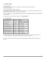
3 Software Update
3.1
Update software:
Use the 240-Series EST to set the new confi gurations on 230-Series and 240-Series machines.
(after the S/N break below)
The new cab machines start at S/N YDG218540
Software update required is: UCM1 - V33.33.0.0 or newer, UCM2 - V33.34.0.0 or newer (for S/N above and newer)
Display Software (Part # 48109497 Combine Axial Flow) V30.8.0.0
Machines <YDG218540 do not get software update and would require the spreader/chopper speed sensor placed on
the 7-tooth target
3.2
Use EST to change the Machine Confi guration for “
Residue System
”
3.4
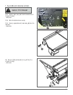
Calibrate the windrow door and spread control actuators following the instructions in the Combine Owner’s
Manual
3.3
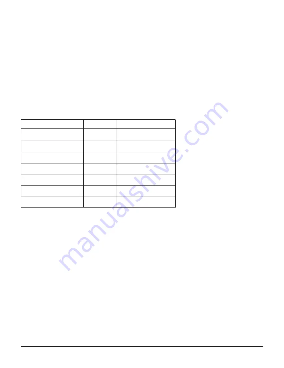
Set confi guration to:
Confi guration Name
Type ID
Value
Residue System*
0x209C
Windrow Door
0x20A1
1 (installed)
Left Spread Defl ector
0x2112
1 (installed)
Center Spread Defl ector
0x2113
0 (not installed)
Right Spread Defl ector
0x2114
1 (installed)
Hood Mount Chopper
0x2111
1 (installed)
Windrow Chute Extension
0x20A4
0 (not installed)
*For MY14 and newer machines with existing 90cc spreader motor and 32cc pump with in cab adjust, Value = 6
*For MY13 UCM machines with existing 74cc spreader motor and 28cc pump, Value = 3
*Impeller with 32cc Pump &
90cc Motor In-CAB Adjust*