background image

25

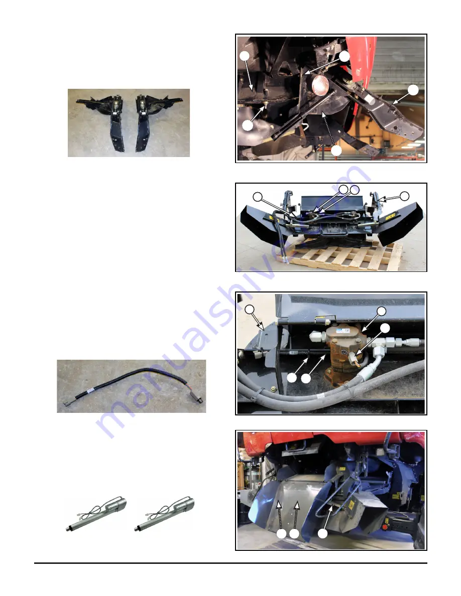
4.3.7

   Remove hardware (

G6

) mounting the spreader 

arms (

G4

) to the combine rails (

H

) - both sides

- not to be reused

G4

G6

G6

G6

H

4.3.8

   Remove speed sensor (

J

) from left side hydraulic 

motor (

K

) on the spreader assembly (

G

)

4.3.8.1

   Cut off nylon ties (

L

) securing the speed sensor 

wire harness (

J1

) to the spreader assembly (

G

)

- to be reinstalled in a different location for the MAV straw  

chopper

L

J

J1

G

K

G

J

J1

K

4.3.9

   Actuator Removal - if equiped

4.3.9.1

   Remove large acutators (

M

) x2  from spreader 

assembly

- to be reinstalled on MAV straw chopper

M

M

M1

Summary of Contents for Case IH AFX 7230 Series

Page 1: ...1 TM Case IH AFX 7120 9120 7230 9230 7240 8240 9230 Series Removal Guide for Installation of Redekop MAV Straw Chopper CS0133 01_V2_Oct_2016...

Page 2: ...Installation of Redekop MAV Straw Chopper Table of Contents Section Safety 0 Left Rear Side Access Panel 1 Factory Drive and Components 2 Ladder Assembly 3 Straw Spreader Assembly 4 Internal Straw Doo...

Page 3: ...4 Straw Spreader 5 Internal Straw Door 6 Internal Straw Deflectors 7 Sieve Extension 8 Hydraulic Oil Level 1 6 2 4 7 5 3 Case IH AFX 230 7240 8240 Series Factory Component Removal Guide for Installat...

Page 4: ...rualic Cap 12 FORS Fitting Qty 2 found in box CS849S bag CS840S Parts required to be installed during the removal procedure If you are preparing the combine prior to the arrival of the MAV Strawchoppe...

Page 5: ...5 litres of capacity required for section 4 1 Blocking 10 x 8 x 43 inches 250 x 200 x 1100 mm required for section 0 13 2 Pallet 40 x 70 inches 1000 x 1800 mm required for section 4 3 Locking Mechanis...

Page 6: ...ON safety signs are located near specific hazards or precautionary areas in this manual 0 4 Follow Safety Instructions 0 4 1 Carefully read all safety messages in this manual and on your machine Keep...

Page 7: ...unning 0 6 Work In Ventilated Area 0 6 1 Engine exhaust fumes can cause sickness or death If it is necessary to run an engine in an enclosed area remove the exhaust fumes from the area with an exhaust...

Page 8: ...ay result Doctors unfamiliar with this type of injury should reference a knowledgeable medical source 0 10 Dispose of Waste Properly 0 10 1 Improperly disposing of waste can threaten the environment a...

Page 9: ...sting or potential hazards in surroundings or working conditions which may be hazardous or dangerous to employees shall determine appropriate Personal Protective Equipment required for this assembly P...

Page 10: ...13 1 Shut off engine remove keys A from the com bine cab D C 0 13 2 Block B wheels on level ground 0 13 3 Lift up the left rear side access panel C 0 13 4 Turn Master Power Off D 0 13 Master Power A...

Page 11: ...nect wire harness A1 from light 1 1 2 Remove hardware A2 x2 mounting the left rear side access panel A to the combine upper brackets 1 1 3 Remove head of gas springs A3 x 2 from ball studs on inner mo...

Page 12: ...CNH 86517680 not to be reused 2 2 Inner Belt Removal from drive pulley 2 2 1 Remove inner belt C from drive pulley D leave loose do not remove from combine 2 3 Drive Pulley Removal 2 3 1 Remove cente...

Page 13: ...13 D1 D3 2 3 3 Replace center bolt and washer D1 onto shaft D3 D4 2 3 4 Ensure key D4 remains in shaft D3 secure key in place with tape if required...

Page 14: ...nting plates E1 Do Not scratch the glamour panel A place on or cover with a protective wrap Glamour panel to be reinstalled with the MAV straw chopper ladder B A C E D D B 3 1 3 Ladder Handle Assembly...

Page 15: ...ce 3 2 1 2 Remove clip B1 from top end of gas spring B 3 2 2 Unbolt lower gas spring head B2 from ladder pivot tube plate C1 3 2 2 1 Hold gas spring B and angle out until the top end releases from the...

Page 16: ...ck side of the ladder E mounting the nylon blocks H x2 around the pivot tube C to be reinstalled on new pivot frame reassemble hardware onto blocks C H H H1 E 3 2 5 Remove mounting hardware G1 x 2 att...

Page 17: ...r bolt J mounting the pivot tube plate C1 to the combine mount plate C2 both sides Pivot Tube C will now slide out not to be reused C J C1 C2 3 4 3 Remove hardware K1 x3 attaching the pivot tube block...

Page 18: ...g fluid under pressure can penetrate the skin causing serious injury Avoid the hazard by relieving pressure before disconnecting hydraulic or other lines Tighten all connections before applying pressu...

Page 19: ...ber hydraulic hoses B x2 from bulkhead plate C below DEF tank hoses will leak upon removal place a pail below to catch any fluids 4 1 6 Remove fitting A1 from one 1 of the steel hydraulic lines A just...

Page 20: ...20 4 1 7 Thread in fitting A1 into both rubber hydraulic lines B to connect together B B B A1 B A1...

Page 21: ...E to connectors E1 4 2 Disconnect Electrical Harness from Spreader 4 2 1 Disconnect spreader electrical harness connectors E1 x3 from combine harness at locations noted along spreader at proximity se...

Page 22: ...uture ladder sensor Sensor F1 to be reused on the future Straw Door 4 2 3 1 Label sensors for future identification reconnect sensors F2 and F1 to wiring harness if disconnected when removed 4 2 4 Bun...

Page 23: ...nd Apparel must be worn Pinching Hazard 4 3 Straw Spreader Removal 4 3 1 Move deflectors G1 inwards 4 3 1 1 Lock deflectors G1 in place with pin G2 both sides G1 G1 G G1 G2 4 3 2 Rotate spreader assem...

Page 24: ...3 3 1 Secure blocking and spreader onto the pallet This component weighs 500 lbs 230 kg Use a forklift with appropriate capacity 4 3 4 Remove hydraulic hose clamp G3 from top left spreader mounting ar...

Page 25: ...draulic motor K on the spreader assembly G 4 3 8 1 Cut off nylon ties L securing the speed sensor wire harness J1 to the spreader assembly G to be reinstalled in a different location for the MAV straw...

Page 26: ...locks E to the combine internal side wall F both sides 5 2 4 Pry pivot tube blocks E off of welded studs E2 blocks to be reinstalled for new straw door 5 2 5 Slide door out not to be reused D E E1 F E...

Page 27: ...ardware A2 from lower deflector mounting tab attached to combine side wall 6 1 3 Remove hardware A3 x3 attaching side deflector to top deflector plate C Top Deflector Plate C stays in place 6 1 4 LOOS...

Page 28: ...1 1 1 Turn Sieve Extension A over 7 1 2 Remove hardware C1 mounting the rubber strap C to the sieve extension pivot bracket D not to be reused B 7 1 3 Remove hardware D1 x2 mounting the pivot bracket...

Page 29: ...29 7 2 Sieve extension curtain assembly removal if equipped 7 2 1 Remove hardware F1 x2 mounting the curtain assembly F to the underside of the grain loss monitor G both sides not to be reused G F1 F...

Page 30: ...ore starting and moving the combine Oil level can be checked through the sight glass A located on the top rear deck The oil level should at a minimum reach the bottom of the sight glass 8 2 If necessa...

Reviews: