SRP - User manual
Ref.: RX182/006
Version 01/2017 - English
This document must not be reproduced nor information therein disclosed without our authorization
Page 15 / 28
6
MOUNTING OF THE SRP ON THE MACHINE FRAME
WARNING! HANDLING OPERATIONS.
The SRP unit can be handled by the main housing, the bevel box shafts, the fixing flange
holes or, with lifting rings by the output flange tapped holes.
First of all, clean the mounting surfaces to be fitted together: gearbox flange, pilot diameter, machine
surface, driven part on output.
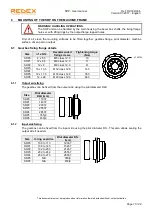
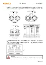
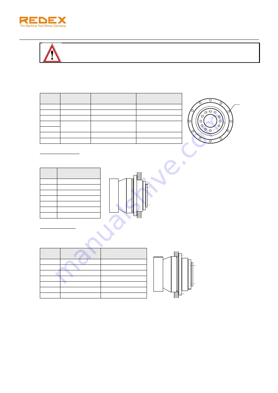
6.1 Gearbox fixing flange details
Size
n1 x D3c
Recommended
fixing screws
Tightening torque
(Nm)
SRP0
8 x 5,5
M5 class 12.9
10
SRP1
12 x 6,5
M6 class 12.9
17
SRP2
12 x 9
M8 class 12.9
41
SRP3
16 x 13,5
M12 class 12.9
145
SRP4
SRP5
12 x 17,5
M16 class 12.9
355
SRP6
12 x 22
M20 class 12.9
690
6.1.1
Output side fixing
The gearbox can be fixed from the output side using the pilot diameter D2d.
Size
Pilot diameter
D2d (mm)
SRP0
110h7
SRP1
140h7
SRP2
200h7
SRP3
255h7
SRP4
285h7
SRP5
355j6
SRP6
450j6
6.1.2
Input side fixing
The gearbox can be fixed from the input side using the pilot diameter D1c. This also allows sealing the
output side if needed.
Size
O-ring seal dim.
Pilot diameter D1c
(mm)
SRP0
108 to 113
120h7
SRP1
138 to 145
152h7
SRP2
192 to 200
212h7
SRP3
232 to 242
255h7
SRP4
259 to 270
285h7
SRP5
N/A
355j6
SRP6
N/A
450j6
n1 x D3c


