SRP - User manual
Ref.: RX182/006
Version 01/2017 - English
This document must not be reproduced nor information therein disclosed without our authorization
Page 23 / 28
8.2 Shaft alignment
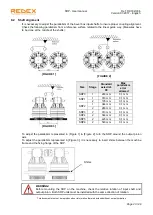
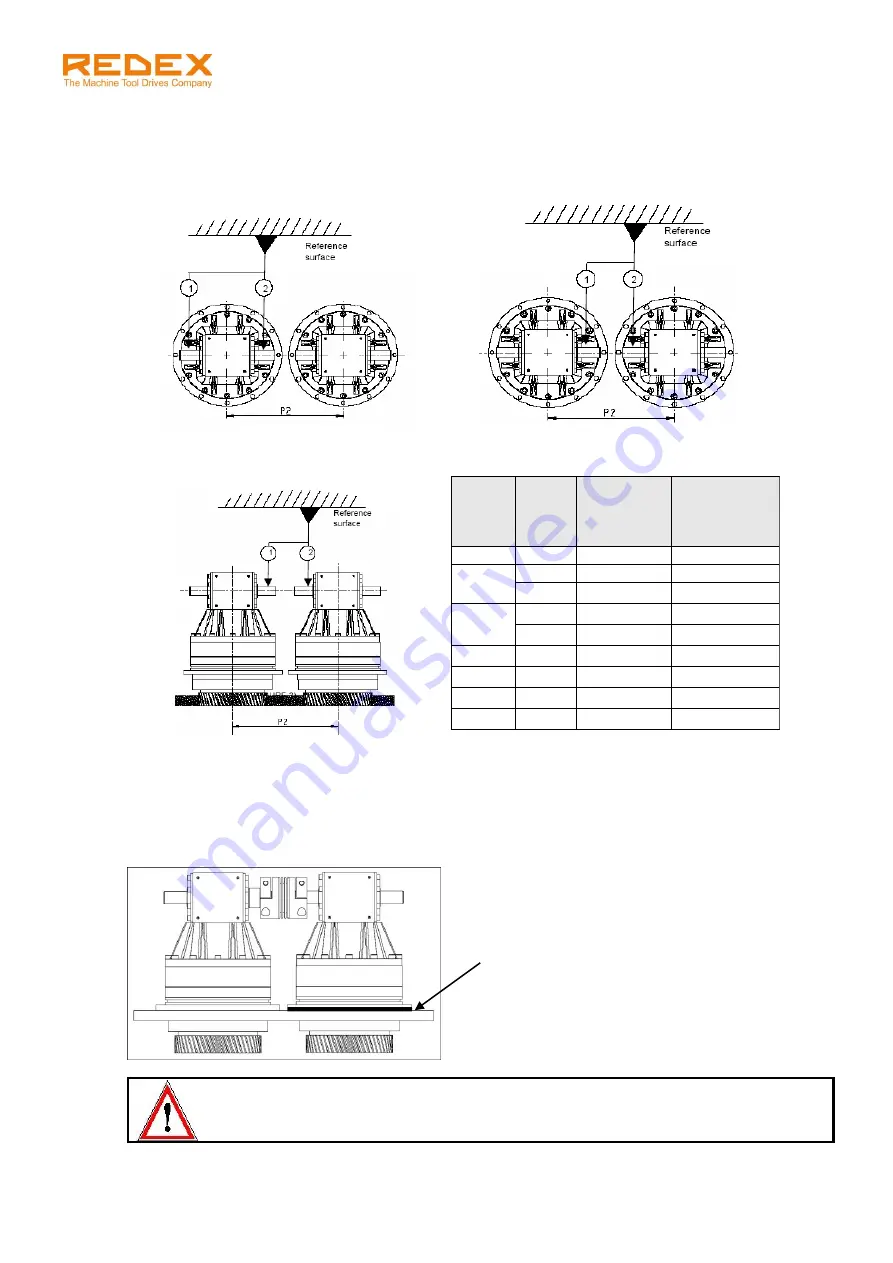
It is necessary to adjust the parallelism of the bevel box input shafts to insure proper coupling alignment.
Check the following parallelism from a reference surface related to the linear guide way. (Measures have
to be done at the middle of the shafts):
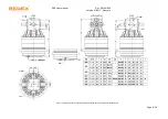
[FIGURE 1]
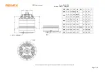
[FIGURE 2]
[FIGURE 3]
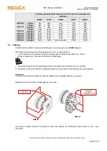
Size
Stage
Standard
axis dist.
P2
Max
parallelism
error
allowed
SRP0
1
263 mm
0,1 mm
SRP1
1
313 mm
0,1 mm
2
195 mm
0,1 mm
SRP2
1
344 mm
0,1 mm
2
263 mm
0,1 mm
SRP3
2
313 mm
0,1 mm
SRP4
2
344 mm
0,1 mm
SRP5
2
425 mm
0,1 mm
SRP6
2
540 mm
0,1 mm
To adjust the parallelism represented in [Figure 1] & [Figure 2], turn the SRP around the output pinion
axis.
To adjust the parallelism represented in [Figure 3], it is necessary to insert shims between the machine
frame and the fixing flange of the SRP.
WARNING!
Before mounting the SRP on the machine, check the relative rotation of input shaft and
output pinion. Both SRP units must be installed with the same direction of rotation.
Shims


