SRP User manual
Ref.: RX182/006
Version 01/2017 - English
This document must not be reproduced nor information therein disclosed without our authorization
Page
3
/ 28
2
TECHNICAL DATA
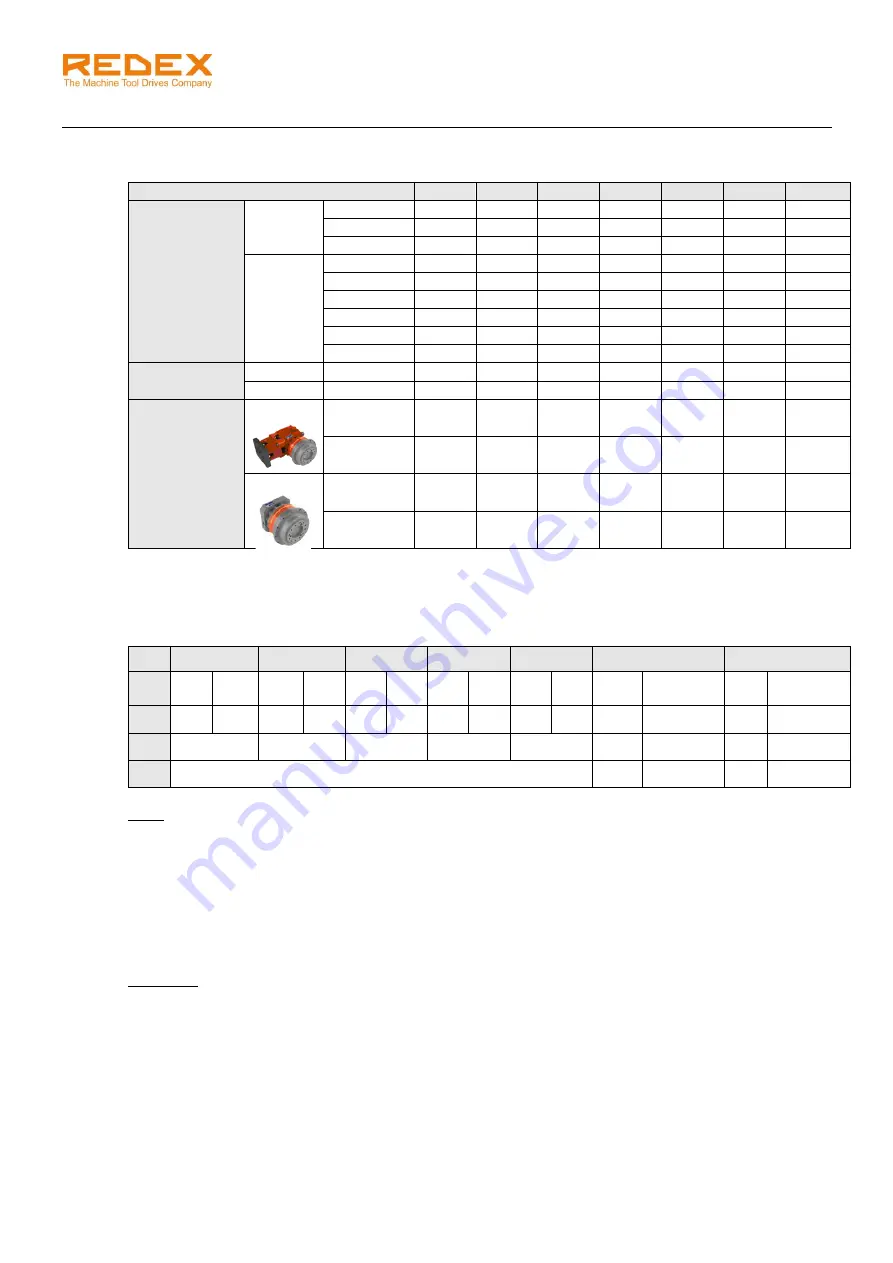
2.1 Gearbox
SRP0
SRP1
SRP2
SRP3
SRP4
SRP5
SRP6
Maximum
acceleration
output torque
(Nm)
1 stage
i=5
350
648
1750
-
-
-
-
i=7
350
665
1750
-
-
-
-
i=10
350
473
1400
-
-
-
-
2 stages
i=17
-
683
1838
3238
6125
-
-
i=21
-
534
1400
2625
6125
7520
16585
i=31
-
753
2100
3850
6300
10050
18590
i=46
-
473
1400
2468
4480
8800
17128
i=61
-
656
2013
2695
4970
8800
13330
i=91
-
473
1400
2695
4970
8800
17128
Max. input
speed (rpm)
1 stage
i=5, 7, 10
6000
5000
4000
-
-
-
-
2 stages
i=21 to 91
-
6000
6000
5000
4000
4000
3500
Approx.
Weight (kg)
SRP.R
1 stage
11.3
18.3
41.2
-
-
-
-
2 stages
-
17
40.2
83.5
144
530
635
SRP.M
1 stage
6.8
13.8
33.7
-
-
-
-
2 stages
-
14.9
35.7
76.0
123
238
510
2.2 Output pinion
The SRP unit can be delivered with an output pinion fixed on the output flange. The pinion has the
following characteristics.
OP 0
OP1
OP2
OP3
OP4
OP5
OP6
Z
45
36
42
35
52
39
45
36
42
35
15
16
14
15
Mo
2
2.5
2.5
3
3
4
4
5
5
6
8
8
10
10
D
02
95.49
111.41
165.52
190.99
222.82
128
127.32
150
148.54
b
0
19°31’42”
0°
19°31’42”
0°
19°31’42”
Note:
Data are subjected to change without prior notices.
2.3 Mounting position nomenclature
Output flange position / motor flange position (if different) with:
-
B5 horizontal
-
V1 vertical down
-
V3 vertical up
Examples:
V1/B5: output flange vertical down / motor flange horizontal
B5: output flange & motor flange horizontal


