19
16.0 OPTIONS, WHEEL KIT.
The part number for a full transport kit for the 7316 is 9200100. This kit will be separately delivered
and can be mounted to a standard 3-point linkage machine. Generally speaking, a machine with
wheel kit will reduce the minimum horsepower required by 5 HP It also can be taken off quickly, so
the machine can be used either way
16.0.1 MOUNTING THE WHEELKIT TO THE MACHINE
.
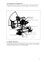
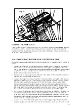
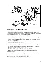
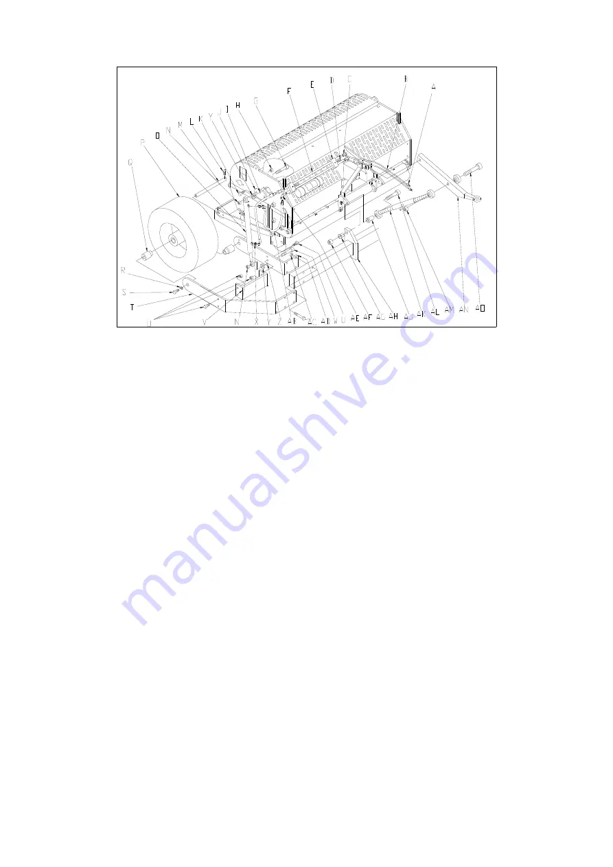
On attached pages a detailed sketch is given from the assembly of the wheelkit of the 7316. Work as
follows:
1.
Assemble main beam AH with bearing bushes AG, together with the toplinks AK with distance
bushes AJ with bolt AL to both Verti-Drain bottom link strip holes and tighten it with nut AF.
Use the front hole at the Verti-Drain as drawn in attached sketch. The main beam AH should face
away from the machine (exactly as drawn). After the beam with the toplinks are fitted and
tightened, it should pivot around bushes AG.
2.
Next assemble the wheel support plates AD and T with bolt/nut AC. Note that AD is only fitted
with four bolts. Do not tighten the bolt/nut AC.
3.
Assemble the bridge V in-between T and AD. V is bolted with two bolts/nuts U to T at one side
and with one bolt W /nut ¾” N + one bolt/nut U to AD at the other side. The hydraulic cylinder
O bottom side is assembled at the same bolt W. Note that washer Y have to be assembled
between wheel support AD and the hydraulic cylinder rod end, otherwise the rod will hit the
support AD. (Check this after full assembly). Do not tighten all bolts/nuts yet. Another important
item is that bolt W/nut N should be mounted at the bottom hole Z at each side of the machine.
The top hole is not used, but is drilled, because we wanted identical parts left and right.
4.
The top end of the hydraulic cylinder is mounted with bolt G and nut N to plate J. A washer Y is
needed between the hydraulic cylinder and plate J. Plate J fits with two bolts/nuts K/H to the
standard holes at the side of the machine. Remove the standard zinc plated protection plate, and
use plate J in stead. Note that hole I should face up at each side of the machine, since plate J is
not symmetric. Do not tighten the bolts/nuts.
5.
Assemble wheel P with shaft M through the holes of wheel support strips AD and T. First fit a
distance bush Q to each side of the wheel into the wheel bearings.. Lock pin L should fit the lock
Fig.10.

