background image


12


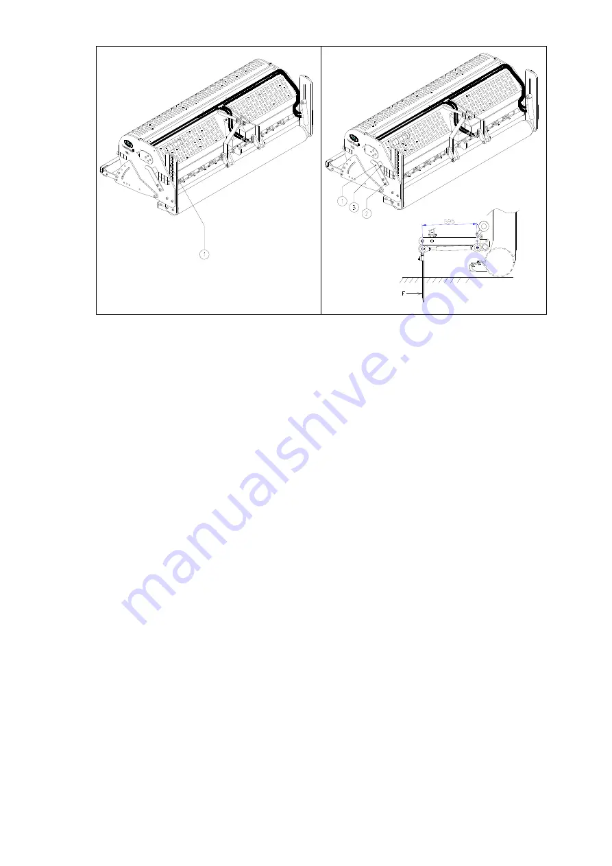
Fig. 11   


Fig. 12


4.0   OPERATING-DEPTH ADJUSTMENT 

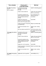
The operating depth can be adjusted when the machine is raised (before start of use) 
or during operation in the ground when the machine is in use, see fig. 11.


The machine is equipped with a hydraulic operating-depth adjustment that can be 
operated from the tractor by activating the hydraulic output of the tractor. 
The label (1) on the side of the machine indicates the depth setting. 
 

Make sure that both sides of the machine raise or lower evenly. 


If not, stop the movement immediately to prevent damage to the machine. 
To remove trapped air from the hydraulic operating-depth adjustment, see chapter 2.0 
points 12 through 14. 

The depth-adjustment on the decals only applies when 400 mm (16”) long pins are used. 
When shorter pins are used, subtract the difference in length, compared to 400 mm (16”), 
from the value shown on the decals.


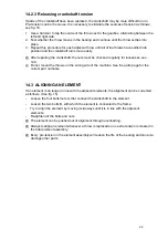
5.0   PIN ANGLE ADJUSTMENT


All pins can simultaneously be adjusted with one handle (1), which is located on the side of 
the machine; see fig. 12. Lift the machine above the ground and loosen counter nuts (2) on 
both sides of the machine. Adjust the angle by turning the handle (1). The angle can be read 
on indicator (3). Then retighten counter nuts (2).


An angle of 90 degrees means almost no draught. This is required for hollow pins and is 
advised for the 8 mm (5/16”) pins.


From 90 to 75 degrees means more draught. This is advised for solid pins and is 
dependent of the ground conditions, the pin size and the client’s preference.


At 90 degrees, the pins only go straight into the ground if the machine is correctly 
installed, see fig. 8. If this is not correct, force F can be produced, see fig. 12, which will 
damage the machine.


The length of the assembled drawbar must be 595 mm (23.4”), which can be 
calibrated using shims. (see parts page)


Summary of Contents for Verti-Drain 7621

Page 1: ...MANUAL IS CAREFULLY READ BEFORE THE VERTI DRAIN IS USED 1735 English 911 120 040 Operator and Parts manual Verti Drain Model 7621 Serial number Translation of the original operating instructions Kweke...

Page 2: ...order to be able to handle any future claims This user manual offers many instructions numbered in sequence This sequence should be observed An asterisk indicates a safety instruction An indicates a t...

Page 3: ...Improper use maintenance or repair of the machine may result in injury to both the user and others This should be avoided Always use the Verti Drain in combination with the proper tractor as described...

Page 4: ...ance adjustments or repairs always switch off the tractor engine first remove the tractor key from the ignition and disconnect the PTO Fig 2 Fig 2 When carrying out any maintenance or repairs make sur...

Page 5: ...Replace them if they are damaged During operation make sure there are NO persons in the danger area of the Verti Drain because they may be injured by moving parts Fig 3 Fig 3 Fig 4 Remain at least 4...

Page 6: ...6 7 Location of safety stickers Fig 7 Fig 7 Used oil grease is harmful to the environment dispose of it according to locally applicable regulations...

Page 7: ...5 0 Pin angle adjustment 12 6 0 Driving speed 13 7 0 Start procedure 14 8 0 Operation of the Verti Drain 15 9 0 Transportation of the Verti Drain 15 10 0 Disconnecting the Verti Drain 15 11 0 Troubles...

Page 8: ...tractor 55 HP with minimum lifting capacity of 2000 kg 4408 lbs Double acting external hydraulic connection Maximum capacity Hole separation 65 mm 2 1 2 Hole separation 130 mm 5 Hole separation 165 m...

Page 9: ...ons 10 Connect the hydraulic hoses to the tractor 11 Raise the machine off the ground 12 Open the valve on the right front side of the machine Detail A by turning it anti clockwise with the included k...

Page 10: ...rect after purchase or when using another tractor carry out the following steps see Fig 10 1 Measure the distance between the PTO connection of the tractor and that of the Verti Drain from groove to g...

Page 11: ...un the machine in the field at a very low speed If the coupling slips stop after 10 seconds If the coupling does not slip loosen the bolts further or proceed to the annual maintenance see point 4 belo...

Page 12: ...difference in length compared to 400 mm 16 from the value shown on the decals 5 0 PIN ANGLE ADJUSTMENT All pins can simultaneously be adjusted with one handle 1 which is located on the side of the ma...

Page 13: ...fore the pin holders are forced upward In fig 13 is a table that shows the relationship between the driving speed the gearbox speed and the hole distance If the driving speed of the tractor for 500 re...

Page 14: ...the hydraulic depth adjustment or with the lifting device of the tractor 3 Disengage the PTO shaft as soon as the pins are out of the ground 4 Raise the machine further until the pins are at least 12...

Page 15: ...he transport of the Verti Drain behind the tractor when travelling on public roads Check the national traffic regulations On open fields a maximum speed of 12 km h 8 mph should be observed because of...

Page 16: ...tact with the ground Wrong pins too much resistance Heavy conditions Change pin size Adjust the operating depth accordingly Use different pin size Adjust the operating depth Water the soil Do not do a...

Page 17: ...depth system See chapter 2 0 points 12 through 14 12 0 MAINTENANCE Time schedule Check point lubricating point Method Before each use Check for loose bolts nuts Connect the machine to the tractor and...

Page 18: ...d listen for any strange noises and movements Use 80W90 Repair any leaks damage Replace seals sealing paste Secure these parts so that they cannot come too close to the PTO After every 50 operating ho...

Page 19: ...uct VERTI DRAIN MODEL 7621 WITH MACHINE NUMBER AS INDICATED ON THE MACHINE AND IN THIS MANUAL to which this declaration relates is according to the stipulation of the 2006 42 EC directive for machines...

Page 20: ...ns contact your dealer who will be happy to provide assistance Fig 15 14 1 TORQUE VALUES In fig 15 the torque values for the most important bolts nuts are shown The bolts and nuts for which no values...

Page 21: ...icone sealant 13 Install a new lock plate and nut VIII For the nut also use Loctite 14 Tighten nut VIII with the torque indicated in figure 15 15 Install the remaining parts in reverse order 16 If the...

Page 22: ...arly for looseness see 12 0 Do not mount the throws on the wrong side of the machine See the parts page for the correct part numbers 14 3 ALIGNING AN ELEMENT If an element is no longer in line with th...

Page 23: ...m pins and the mounting material consisting of a number of bolts and nuts INSTALLATION OF THE TURF HOLD DOWN KIT see fig 18 The ordered set comes with plates 4 or 5 Mount the plates with bolt 3 and nu...

Page 24: ...t in the ground When the angle is adjusted from 90 to 65 degrees the draught movement increases With a 90 degree adjustment there is almost no pin movement created in the ground When the pins are new...

Page 25: ...roller 15 1 2 HOLLOW PINS The ground can be mixed with hollow pins Various sizes are available see the parts page for more information The opening of the pin must be directed toward the rear of the ma...

Reviews: