background image

15

DÉCLARATION DE CONFORMITÉ

Le fabricant certifi e la conformité des appareils aux normes 2004/108/ES, 2006/95/ES, 

2006/95/ES

 à la 

loi n° 616/2006 sb., 17/2003 sb. et aux décrets applicables. L‘installation doit être eff ectuée dans le respect 

des normes en vigueur. Attention: le fabricant décline toute responsabilité en cas de dommages, directs ou 

indirects, causés par une mauvaise installation, par une utilisation, des interventions ou des modifi cations 

impropres,  par  un  entretien  insuffi  sant,  ainsi  qu‘en  cas  de  dommages  dérivant  des  causes  mentionnées 

dans les conditions de vente. L‘appareil objet de la présente notice est prévu pour un usage professionnel, 

aussi  son  utilisation  doit-elle  être  confi ée  à  un  personnel  possédant  les  compétences  nécessaires  à  cet 

eff et. L‘utilisateur ne doit procéder à aucune intervention ni à aucune modifi cation sur les parties réglées et 

protégées par le fabricant ou autre personnel autorisé à cet eff et.

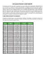
CARACTÉRISTIQUES TECHNIQUES 

L‘étiquette  sur  laquelle  fi gurent  les  caractéristiques  techniques  est  apposée  sur  la  partie  postérieure  de 

l‘appareil. Avant de procéder à l‘installation, prendre connaissance du schéma électrique et de toutes les 

informations que contient la présente notice.

MODEL

DIMENSIONS

(CM)

PUISSANCE (KW)

TENSION    (V)

CAPACITÉ

(L)

TRAVAIL CAPA-

CITÉ (L)

FE – 04

18 x 42 x 30 v

2,1 / 230 V 

4 – 5

4 – 5

FE – 44

36 x 42 x 30 v

2 x 2,1 / 230 V 

2 x 4 – 5

2 x 4 – 5

FE – 04 S

18 x 42 x 30 v

3 / 230 V 

4 – 5

4 – 5

FE – 44 S

36 x 42 x 30 v

2 x 3 / 230 V 

2 x 4 – 5

2 x 4 – 5

FE – 07

27 x 42 x 30 v

3 / 230 V 

7 – 8

5

FE – 07 V

27 x 42 x 37 v

3 / 230 V 

7 – 8

7 – 8

FE – 77

54 x 42 x 30 v

2 x 3 / 230 V 

2 x 7 – 8

2x 5

FE - 77 V

54 x 42 x 37 v

2 x 3 / 230 V 

2 x 7 – 8

2 x 7 – 8

FE – 07 T

27 x 42 x 30 v

6 / 400 V (3 N)

7 – 8

5

FE – 07 VT

27 x 42 x 37 v

6 / 400 V (3 N)

7 – 8

7 – 8

FE - 77

54 x 42 x 30 v

2 x 3 / 230 V

7 – 8

2x 5

FE – 77 T

54 x 42 x 30 v

2 x 6 / 400 V / (3 N)

2 x 7 – 8

2x 5

FE – 77 VT

54 x 42 x 37 v

2 x 6 / 400 V / (3 N)

2 x 7 – 8

2 x 7 – 8

FE – 74

45 x 42 x 30 v

2 + 3 / 230 V 

4 –5 + 7 – 8

(4-5) + 5

FE - 08

21 x 52 x 30 v

3,4 / 230 V

8

5

FE - 08 V

21 x 55 x 30 v

3,4 / 230 V

8

8

FE – 10 T

36 x 42 x 37 v

8,1 / 400 V / (3 N)

10

10

FE – 1010 TD

72 x 42 x 37 v

2x8,1 / 400 V / (3 N)

2 x 10

2 x 10

FE - 30 

54 x 45 x 37 v

9 / 400 V / (3 N)

16

16

FE - 60 

67 x 65 x 37 v

15 / 400 V / (3 N)

30

30

FE - 60/P

67 x 65 x 90 v

15 / 400 V / (3N)

30

30

FE - 88

42 x 52 x 30 v

6,8 / 230 V

2 x 8

2 x 5

FE - 88 V

42 x 55 x 30 v

6,8 / 230 V

2 x 8

2 x 8

Summary of Contents for FE-04

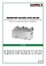
Page 1: ...ON AND USE DIE GEBRAUCHS UND INSTALLATIONSANWEISUNG NOTICE D INSTALLATION ET D EMPLOI Date 2017 FRYERS FE 04 S FE 07 V FE 08 V FE 07 T FE 07 VT FE 10 T D FE 44 S FE 77 V FE 77 T FE 77 VT FE 88 V FE 74...

Page 2: ......

Page 3: ...MODEL DIMENSIONS CM WATTAGE KW VOLTAGE V VOLUME L WORKING VOLUME L FE 04 18 x 42 x 30 v 2 1 230 V 4 5 4 5 FE 44 36 x 42 x 30 v 2 x 2 1 230 V 2 x 4 5 2 x 4 5 FE 04 S 18 x 42 x 30 v 3 230 V 4 5 4 5 FE 4...

Page 4: ...bols and labels There are also appropriate instructions for use In case the packing shows bad handling or damage it must be reclaimed at transporter immediately by writing and signing of a damage prot...

Page 5: ...nt rebalancing etc must be made only when is device disconnected from electricity If it is necessary to have the device connected to the electricity you must keep the highest attention to avoid any in...

Page 6: ...in a safe way When instaling you must respect corresponding project safety and hygienic orders according to EN 061008 re protection of local devices and sources of heat EN 332000 33 2000 4 482 33 200...

Page 7: ...her in one bath Fill the device with frying oil not higher than the line on the side Switch on with main switch B turn the knob E to required position between 90 C 180 C Pilot lamps C and D will light...

Page 8: ...ondence with instructions by quali ed worker in conformity with standards and when somebody handled incompetently the device interventions into inner equipment or the device was operated by non quali...

Page 9: ...t Studieren sie vor der Installation das elektrische Schema der Einschlie ung und alle folgende Informationen durch MODEL ABMESSUNG CM ANSCHLUSSWERT KW SPANNUNG V UMFANG L ARBEITEN UM FANG L FE 04 18...

Page 10: ...den Schalten Sie alle Leitungen Wasser Elektrizit t Gas bei einer St rung oder beim schlechten Lauf aus und rufen Sie authorisierten Service an Der Hersteller verzichtet auf jegliche Verantwortung bei...

Page 11: ...n Polystyren Polyureten PVC Die Bedarfsartikel m ssen sicher installiert werden und sind mit regulierenbaren Beinchen zur Ausgleichen der H he und der Unebenheiten eingestattet Die Ger te m ssen in ei...

Page 12: ...richt Die Erdungszuleitung gelbgr n darf nicht durch diesen Schalter unterbrochen sein Der Zuleitungskabel mu in jedem Fall so angebracht sein dass er in keinem Punkt einer um 50 C h herer Temperatur...

Page 13: ...Schalten Sie mit dem Hauptschalter die Elektrozuleitung drucken Sie den Schalter B und stellen Sie mit dem Beherrschenr dchen E die verlangte Temperatur in einer Spanne von 90 C bis 180 C ein Die Kon...

Page 14: ...EHEN SOLL Schalten sie die elektrische Stromleitung ab und rufen die Serviceorganisation des Verk ufers an Wie man eine Stahlgrillplatte p egen soll die Grillplatte einheizen Abschalten mit einem Spac...

Page 15: ...de l appareil Avant de proc der l installation prendre connaissance du sch ma lectrique et de toutes les informations que contient la pr sente notice MODEL DIMENSIONS CM PUISSANCE KW TENSION V CAPACI...

Page 16: ...ement la pr sente notice d utilisation L appareil ne peut tre utilis que par le personnel instruit L appareil ne peut tre laiss en marche sans surveillance Il est recomand de faire l appareil controll...

Page 17: ...ocur des pieds r glables EN 06 1008 protection contre incendie des consommateurs d nergie locaux et des mmeteurs de chaleur EN 33 2000 33 2000 4 482 33 2000 4 42 le milieu pour les appareil lectriques...

Page 18: ...de plus que 50 C Avant le branchement au r seau s assurer que le coupe circuit et distribution int rieure peuvent endurer la charge de l appareil voir la plaque la mise la terre fonctionne selon les n...

Page 19: ...s et sal s apr s friture Appuyer sur l interrupteur principal B amener la commande gradu e E de r glage du thermostat sur la temp rature voulue au bout de quelques minutes une fois la temp rature voul...

Page 20: ...avec la spatule peut tre metallique positionn e plat pas sur l ar te utiliser l eau avec le d tergent peut tre le RM gril et enlever la salet r siduelle et les d p ts utiliser l eau propre avec du vin...

Page 21: ...21 DIMENSION PLANS MASSSKIZZEN DIMENSIONS 1...

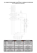
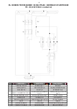
Page 22: ...R 2 MAIN SWITCH SCHALTER INTERRUPTEUR 12 SAFETY THERMOSTAT 230 C SICHERHEITSTHERMOSTAT 230 C THERMOSTAT DE S CURIT 230 C 14 GREEN WARNING LIGHT GR N KONTROLLEUCHT VOYANT VERTE 11 THERMOSTAT THERMOSTAT...

Page 23: ...2 MAIN SWITCH SCHALTER INTERRUPTEUR 12 SAFETY THERMOSTAT 230 C SICHERHEITSTHERMOSTAT 230 C THERMOSTAT DE S CURIT 230 C 14 GREEN WARNING LIGHT GR N KONTROLLEUCHT VOYANT VERTE 11 THERMOSTAT THERMOSTAT...

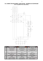
Page 24: ...C THERMOSTAT DE S CURIT 230 C 14 GREEN WARNING LIGHT GR N KONTROLLEUCHT VOYANT VERTE 11 THERMOSTAT THERMOSTAT THERMOSTAT 13 ORANGE WARNING LIGHT ORANGE KONTROLLEUCHT VOYANT ORANGE 8 RELAY RELAIS RELA...

Page 25: ...C THERMOSTAT DE S CURIT 230 C 14 GREEN WARNING LIGHT GR N KONTROLLEUCHT VOYANT VERTE 11 THERMOSTAT THERMOSTAT THERMOSTAT 13 ORANGE WARNING LIGHT ORANGE KONTROLLEUCHT VOYANT ORANGE 8 RELAY RELAIS RELA...

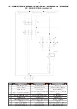
Page 26: ...TAT 230 C THERMOSTAT DE S CURIT 230 C 14 GREEN WARNING LIGHT GR N KONTROLLEUCHT VOYANT VERTE 11 THERMOSTAT THERMOSTAT THERMOSTAT 13 ORANGE WARNING LIGHT ORANGE KONTROLLEUCHT VOYANT ORANGE 8 RELAY RELA...

Page 27: ...2 MAIN SWITCH SCHALTER INTERRUPTEUR 12 SAFETY THERMOSTAT 230 C SICHERHEITSTHERMOSTAT 230 C THERMOSTAT DE S CURIT 230 C 14 GREEN WARNING LIGHT GR N KONTROLLEUCHT VOYANT VERTE 11 THERMOSTAT THERMOSTAT...

Page 28: ...2 MAIN SWITCH SCHALTER INTERRUPTEUR 12 SAFETY THERMOSTAT 230 C SICHERHEITSTHERMOSTAT 230 C THERMOSTAT DE S CURIT 230 C 14 GREEN WARNING LIGHT GR N KONTROLLEUCHT VOYANT VERTE 11 THERMOSTAT THERMOSTAT T...

Page 29: ...TAT 230 C THERMOSTAT DE S CURIT 230 C 14 GREEN WARNING LIGHT GR N KONTROLLEUCHT VOYANT VERTE 11 THERMOSTAT THERMOSTAT THERMOSTAT 13 ORANGE WARNING LIGHT ORANGE KONTROLLEUCHT VOYANT ORANGE 8 RELAY RELA...

Page 30: ...30...

Reviews: