background image

6

SAFETY MEASURES FROM THE STANDPOINT OF THE FIRE 

PROTECTION ACCORDING TO EN 061008 ČL. 21


• only adults can operate the device

• device must be safely used in common surroundings according to EN 332000-4-462; EN 332000-4-42. You 

must switch the gas device off  under the circumstances leading: to the danger of the temporary rise of the 

combustion gas or steam or during works when there is a big possibilityof rise ot the temporary fi  re danger 

or explosion (for example: to stick linoleum, PVC etc.).

• before you start to instal the device you must get the licence for connection to the gas feeder from the 

gasworks

• device must be placed so as to stand or hang on the noncombustible surface which is on each side 10 

cm larger than the device. No subjects from combustible materials can be placed directly on the device 

or in distance which is shorter than safety distance (the shortestdistance is 50 cm in the direction of the 

heat emission and 10 cm in other directions).- safety distances from various materials of diff erent degree of 

combustion and information about the degree of comb. of common building materials - see chart:

Chart:

Combustion degree of building materials classifi ed according to the combustion degree of materials and 

products (EN 730823)

A noncombustible  


granit, sandstone, concretes,bricks, ceramic wallfacing tiles, plaster

B uneasily combustible  

akumine, heraklite, lihnos, itavere

C1 hardly combustible  

leafy wood, plywood, sirkoklit, rare paper formica 

C2 middle combustible  

fi breboards, solodure, cork boards, rubber,fl oor-coverings

C3 easily combustible  

wood-fi breboards, polystyrene,polyurethane, PVC

Devices must be instalated in a safe way. When instaling you must respect corresponding project, safety and 

hygienic orders according to:

• EN 061008 fi re protection of local devices and sources of heat

• EN 332000 (

33 2000-4-482; 

33 2000-4-42)

 surrounding for electric devices ČSN EN 1775 Gas supplying  

• Gas fi  ttings in the buildings - the highest operational pressure < 5 bar - operation demands 

• § 10 law nr. 185/2001 Sb. about waste

CONNECTION OF THE ELECTRIC CABLE TO THE ELECTRICITY

Instalation of electric feeder - This feeder must be separetely protected by a safety fuse according to the 

specifi c electric stream which depends on the wattage of the instaled device. Check the wattage on the label 

at the back of the device. Connect the device directly to the electricity but you must put the switch between 

the device and electric net. The switch must be placed in min. distance 3 mm between the particular contacts 

according to the standards and loading. The feeder of grounding (yellow-green) cannot be interrupted by this 

switch. In every case feeding cable must be placed so that no point of the cable will reach the temperature 

which is 50°C higher than the temperature of the surrounding. Before connecting the device check that:

• safety fuse of the feeder and inner mains can stand the loading of the device (see label of the matrix)

• mains are equipped with eff ective grounding according to standards (ČSN) and conditions given by law

• socket or switch of the feed is well accessible from device 

We  refuse  any  responsibility  in  case  of  not  respecting  above  mentioned  rules.  Before  the  fi rst  use  it  is 

necessary to remove all the protection foil and to clean the device - see chapter „cleaning and maintenance“. 

Maintenance: We recommend to have the device checked once a year by the proff esional service. Only 

qualifi ed or competent persons can do interventions in the product.

Summary of Contents for FE-04

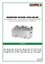
Page 1: ...ON AND USE DIE GEBRAUCHS UND INSTALLATIONSANWEISUNG NOTICE D INSTALLATION ET D EMPLOI Date 2017 FRYERS FE 04 S FE 07 V FE 08 V FE 07 T FE 07 VT FE 10 T D FE 44 S FE 77 V FE 77 T FE 77 VT FE 88 V FE 74...

Page 2: ......

Page 3: ...MODEL DIMENSIONS CM WATTAGE KW VOLTAGE V VOLUME L WORKING VOLUME L FE 04 18 x 42 x 30 v 2 1 230 V 4 5 4 5 FE 44 36 x 42 x 30 v 2 x 2 1 230 V 2 x 4 5 2 x 4 5 FE 04 S 18 x 42 x 30 v 3 230 V 4 5 4 5 FE 4...

Page 4: ...bols and labels There are also appropriate instructions for use In case the packing shows bad handling or damage it must be reclaimed at transporter immediately by writing and signing of a damage prot...

Page 5: ...nt rebalancing etc must be made only when is device disconnected from electricity If it is necessary to have the device connected to the electricity you must keep the highest attention to avoid any in...

Page 6: ...in a safe way When instaling you must respect corresponding project safety and hygienic orders according to EN 061008 re protection of local devices and sources of heat EN 332000 33 2000 4 482 33 200...

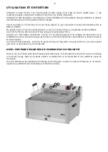
Page 7: ...her in one bath Fill the device with frying oil not higher than the line on the side Switch on with main switch B turn the knob E to required position between 90 C 180 C Pilot lamps C and D will light...

Page 8: ...ondence with instructions by quali ed worker in conformity with standards and when somebody handled incompetently the device interventions into inner equipment or the device was operated by non quali...

Page 9: ...t Studieren sie vor der Installation das elektrische Schema der Einschlie ung und alle folgende Informationen durch MODEL ABMESSUNG CM ANSCHLUSSWERT KW SPANNUNG V UMFANG L ARBEITEN UM FANG L FE 04 18...

Page 10: ...den Schalten Sie alle Leitungen Wasser Elektrizit t Gas bei einer St rung oder beim schlechten Lauf aus und rufen Sie authorisierten Service an Der Hersteller verzichtet auf jegliche Verantwortung bei...

Page 11: ...n Polystyren Polyureten PVC Die Bedarfsartikel m ssen sicher installiert werden und sind mit regulierenbaren Beinchen zur Ausgleichen der H he und der Unebenheiten eingestattet Die Ger te m ssen in ei...

Page 12: ...richt Die Erdungszuleitung gelbgr n darf nicht durch diesen Schalter unterbrochen sein Der Zuleitungskabel mu in jedem Fall so angebracht sein dass er in keinem Punkt einer um 50 C h herer Temperatur...

Page 13: ...Schalten Sie mit dem Hauptschalter die Elektrozuleitung drucken Sie den Schalter B und stellen Sie mit dem Beherrschenr dchen E die verlangte Temperatur in einer Spanne von 90 C bis 180 C ein Die Kon...

Page 14: ...EHEN SOLL Schalten sie die elektrische Stromleitung ab und rufen die Serviceorganisation des Verk ufers an Wie man eine Stahlgrillplatte p egen soll die Grillplatte einheizen Abschalten mit einem Spac...

Page 15: ...de l appareil Avant de proc der l installation prendre connaissance du sch ma lectrique et de toutes les informations que contient la pr sente notice MODEL DIMENSIONS CM PUISSANCE KW TENSION V CAPACI...

Page 16: ...ement la pr sente notice d utilisation L appareil ne peut tre utilis que par le personnel instruit L appareil ne peut tre laiss en marche sans surveillance Il est recomand de faire l appareil controll...

Page 17: ...ocur des pieds r glables EN 06 1008 protection contre incendie des consommateurs d nergie locaux et des mmeteurs de chaleur EN 33 2000 33 2000 4 482 33 2000 4 42 le milieu pour les appareil lectriques...

Page 18: ...de plus que 50 C Avant le branchement au r seau s assurer que le coupe circuit et distribution int rieure peuvent endurer la charge de l appareil voir la plaque la mise la terre fonctionne selon les n...

Page 19: ...s et sal s apr s friture Appuyer sur l interrupteur principal B amener la commande gradu e E de r glage du thermostat sur la temp rature voulue au bout de quelques minutes une fois la temp rature voul...

Page 20: ...avec la spatule peut tre metallique positionn e plat pas sur l ar te utiliser l eau avec le d tergent peut tre le RM gril et enlever la salet r siduelle et les d p ts utiliser l eau propre avec du vin...

Page 21: ...21 DIMENSION PLANS MASSSKIZZEN DIMENSIONS 1...

Page 22: ...R 2 MAIN SWITCH SCHALTER INTERRUPTEUR 12 SAFETY THERMOSTAT 230 C SICHERHEITSTHERMOSTAT 230 C THERMOSTAT DE S CURIT 230 C 14 GREEN WARNING LIGHT GR N KONTROLLEUCHT VOYANT VERTE 11 THERMOSTAT THERMOSTAT...

Page 23: ...2 MAIN SWITCH SCHALTER INTERRUPTEUR 12 SAFETY THERMOSTAT 230 C SICHERHEITSTHERMOSTAT 230 C THERMOSTAT DE S CURIT 230 C 14 GREEN WARNING LIGHT GR N KONTROLLEUCHT VOYANT VERTE 11 THERMOSTAT THERMOSTAT...

Page 24: ...C THERMOSTAT DE S CURIT 230 C 14 GREEN WARNING LIGHT GR N KONTROLLEUCHT VOYANT VERTE 11 THERMOSTAT THERMOSTAT THERMOSTAT 13 ORANGE WARNING LIGHT ORANGE KONTROLLEUCHT VOYANT ORANGE 8 RELAY RELAIS RELA...

Page 25: ...C THERMOSTAT DE S CURIT 230 C 14 GREEN WARNING LIGHT GR N KONTROLLEUCHT VOYANT VERTE 11 THERMOSTAT THERMOSTAT THERMOSTAT 13 ORANGE WARNING LIGHT ORANGE KONTROLLEUCHT VOYANT ORANGE 8 RELAY RELAIS RELA...

Page 26: ...TAT 230 C THERMOSTAT DE S CURIT 230 C 14 GREEN WARNING LIGHT GR N KONTROLLEUCHT VOYANT VERTE 11 THERMOSTAT THERMOSTAT THERMOSTAT 13 ORANGE WARNING LIGHT ORANGE KONTROLLEUCHT VOYANT ORANGE 8 RELAY RELA...

Page 27: ...2 MAIN SWITCH SCHALTER INTERRUPTEUR 12 SAFETY THERMOSTAT 230 C SICHERHEITSTHERMOSTAT 230 C THERMOSTAT DE S CURIT 230 C 14 GREEN WARNING LIGHT GR N KONTROLLEUCHT VOYANT VERTE 11 THERMOSTAT THERMOSTAT...

Page 28: ...2 MAIN SWITCH SCHALTER INTERRUPTEUR 12 SAFETY THERMOSTAT 230 C SICHERHEITSTHERMOSTAT 230 C THERMOSTAT DE S CURIT 230 C 14 GREEN WARNING LIGHT GR N KONTROLLEUCHT VOYANT VERTE 11 THERMOSTAT THERMOSTAT T...

Page 29: ...TAT 230 C THERMOSTAT DE S CURIT 230 C 14 GREEN WARNING LIGHT GR N KONTROLLEUCHT VOYANT VERTE 11 THERMOSTAT THERMOSTAT THERMOSTAT 13 ORANGE WARNING LIGHT ORANGE KONTROLLEUCHT VOYANT ORANGE 8 RELAY RELA...

Page 30: ...30...

Reviews: