REDLAKE MASD, INC.
The trigger input stops the sequence on the frame where the event occurred. You can set the
Trigger Point to record part of the sequence before the event, and the remainder after the event.
This insures that the event shows on Frame 0 of the sequence, which synchronizes the elapsed
time on each frame in the sequence to the event. Refer to 1.3.3 and 1.5.2 for more details.
1.3.2 The Extended Record Option
The Extended Record Option gives longer record times at 60, 125, 250 and 500 frames per
second. Appendix A in this manual shows the standard and extended times available. The
additional times are obtained by reducing the sensor resolution, and are indicated on the display
as 60E, 125E, 250E and 500E.
1.3.3 Stopping a Recording using a Trigger Input
The
Motion
Scope system has a trigger system that detects a signal from an external source and
stops the recording at the frame active at the receipt of the trigger. This enables you to record an
event that occurs very quickly, or happens without warning when the system is unattended. The
active frame when the trigger is received is designated Frame 0. You should always use the
trigger if you want the event coincide with Frame 0, since the stop button has a propagation delay
so Frame 0 will follow the event even if the button is pressed simultaneously.
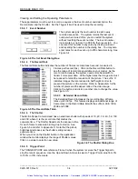
You can set the Trigger Point to determine how many frames you record before the event.
Frames following Frame 0 have positive numbers, and frames preceding Frame 0 have negative
numbers. The camera window shows the elapsed time of each frame in relation to Frame 0, in
positive and negative times. Refer to paragraphs 1.5.2 and 2.8.4 for more information.
The Trigger input is always enabled and held at +5 volts through a 10K resistor. The customer
supplies the trigger signal to the trigger input in one of the following ways. The camera must be
set to receive a rising or falling signal:
1. An open circuit allows the trigger input to stay at +5 volts. The trigger causes a contact
closure that pulls the input down to 0 volts.
2. A closed contact pulls the trigger input down to 0 volts. The trigger opens the contacts
causing the trigger input to rise to +5 volts.
3. The trigger input operates with TTL or CMOS logic at the trigger source. A voltage from the
source is pulled low at the source by a resistor up to 2Kohms in value. The trigger causes
the signal to go to +5 volts to stop recording, and the signal to the trigger input can go as high
as +30 volts.
1.3.4 Synchronization and Controlling the Record Speed
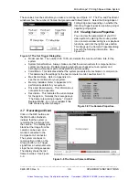
The Phase Lock feature provides a means to synchronize and control the frame rate of the
recorded video. This enables two or more cameras to record different views of the same event
and synchronize the frames in all cameras.
Alternatively a phase lock
pulse, generated by an
external source such as
rotating equipment or a
signal generator to the
Phase Lock In connector,
can synchronize the
recorded frames in a
camera.
The frame rate during
record will follow the
source signal and can be
at any rate up to the
Record Rate setting.
Figure 1-6 The Phase Lock Connections.
_____________________________________________________________________________
9400-0010 Rev S
1-4
02/15/02
Artisan Technology Group - Quality Instrumentation ... Guaranteed | (888) 88-SOURCE | www.artisantg.com


