background image

REDLAKE MASD, INC. 

1.6.2  Analyzing the Motion of a Subject 

The 

Motion

Scope system provides several features to examine a recorded sequence, whether 

the sequence is still in the image memory or has been recorded and retrieved from a computer 
file.  These features are available on all models. 
1.  Slow or Fast Motion.  You can replay the video sequence at speeds of 1 fps to 8000 fps, 

forward and back. 

2.  Viewing Frame by Frame.  You can step through the sequence one click at a time, forward 

and back. 

3.  Fast Forward and Reverse.  Using the Slider on the application window you can go to any 

frame in the video sequence. 

4.  Frame and Time References.  The Playback window shows the frame number currently 

displayed and the time from Frame 0.  The Start button allows you to reset Frame 0 so the 
elapsed times shows for each frame are referenced to the event. 

5.  The Reticle. The Reticle is a position reference that you can superimpose on the video image 

stored in the image memory or a computer file.  The Reticle is a horizontal and a vertical line 
that intersect at a target providing X and Y coordinates. 

6.  Distance and Velocity Measurements.  The reticle enables you to determine distances 

between two points in the picture.  The system must be calibrated by measuring the physical 
distance between two points of interest and entering the distance between the set points in 
the system.  The system then calculates the distance between any two points on the monitor.  
If the points are on different frames, the system also calculates the velocity of the point of 
interest.  
All measurements are in two dimensions perpendicular to the camera.  When you enable the 
Reticle feature, the Reticle button displays the position of the cursor in pixels from the top left 
corner of the window (refer to paragraph 3.5).  You can select distances in inches, feet, 
meters, centimeters, decimeters, or millimeters. 

1.7 Composite 

Out 

The system supplies a video signal that can be viewed on an external monitor or recorded on a 
VCR.  A computer can receive the video signal and store it in a file, provided the computer has a 
video processor board.  The video may be output as an NTSC RS170 signal or a PAL signal. 


_____________________________________________________________________________ 
9400-0010 Rev S 

1-8 

02/15/02 

Artisan Technology Group - Quality Instrumentation ... Guaranteed | (888) 88-SOURCE | www.artisantg.com

Summary of Contents for 1108-0008

Page 1: ... underutilized and idle equipment along with credit for buybacks and trade ins Custom engineering so your equipment works exactly as you specify Critical and expedited services Leasing Rentals Demos In stock Ready to ship TAR certified secure asset solutions Expert team I Trust guarantee I 100 satisfaction All trademarks brand names and brands appearing herein are the property of their respective ...

Page 2: ...hoto for illustration only Your system may differ Redlake MASD Inc 11633 Sorrento Valley Road San Diego California 92121 1010 Telephone 1 800 854 7006 USA and Canada only Outside the USA 858 481 8182 Fax 858 481 6254 Internet www redlake com Artisan Technology Group Quality Instrumentation Guaranteed 888 88 SOURCE www artisantg com ...

Page 3: ...ent generates uses and can radiate radio frequency energy and if not installed and used in accordance with the instructions may cause harmful interference to radio communications However there is no guarantee that interference will not occur in a particular installation If this equipment does cause harmful interference to radio or television reception which can be determined by turning the equipme...

Page 4: ...d performing a power on check Section 3 General Description of the MotionScope PCI System describes the Camera Head and PCI Controller It also describes the application program menus Section 4 Operating the MotionScope PCI System This chapter provides operating procedures for setting up recording and playing back video images Section 5 Processing a Digital Image describes how to use the MotionScop...

Page 5: ...regards to the information contained in this manual including but not limited to implied warranties of merchantability and fitness for a particular purpose Redlake MASD Inc shall not be liable for errors contained herein nor for incidental or consequential damages from the furnishing of this information No part of this manual may be copied reproduced recorded transmitted or translated without the ...

Page 6: ...Image Memory 1 5 1 5 1 Stop Recording 1 5 1 5 2 Stop Recording using the Trigger 1 6 1 5 3 Playing Images from the Image Memory 1 6 1 5 4 Frame Numbers and Elapsed Time Display 1 6 1 5 5 Saving a Sequence in a Computer File 1 7 1 6 Viewing the Image Sequence 1 7 1 6 1 Loss of Frames During Playback 1 7 1 6 2 Analyzing the Motion of a Subject 1 8 1 7 Composite Out 1 8 2 INSTALLING THE MOTIONSCOPE P...

Page 7: ...he Camera Window 3 3 3 5 3 Viewing and Setting the Operating Parameters 3 4 3 5 3 1 Event Number 3 4 3 5 3 2 The Record Rate 3 4 3 5 3 3 Extended Record Rate 3 4 3 5 3 4 The Shutter 3 4 3 5 3 5 Trigger Point 3 4 3 6 Viewing Camera Properties 3 5 3 7 Recording an Event 3 5 3 8 Saving an Event Sequence 3 6 3 8 1 Selecting Frames from the Sequence 3 6 3 8 2 Selecting a File Format 3 6 3 8 3 File Comp...

Page 8: ...1 Saving the Contents of the Image Memory 5 1 5 2 Replaying a Saved File 5 1 5 3 Setting up the Reticle to Measure Motion 5 2 5 3 1 Setting the Reticle Attributes 5 2 5 3 2 Setting and Clearing Data Points 5 2 5 3 3 Calibrating for Distance and Velocity Measurements 5 2 5 3 4 Data 5 2 5 4 Analyzing the Motion of the Subject 5 2 6 MAINTENANCE AND TROUBLESHOOTING 6 1 6 1 Routine Maintenance 6 1 6 2 ...

Page 9: ...Box 3 4 Figure 3 7 The Set Trigger Dialog Box 3 5 Figure 3 8 The Camera Properties 3 5 Figure 3 9 The Record Camera Window 3 5 Figure 3 10 The Save As Dialog Box 3 6 Figure 3 11 Video Compression Options Figure 3 12 Compression Preview 3 7 Figure 3 13 The Playback Menu 3 8 Figure 3 14 The Camera Properties 3 9 Figure 3 15 The Reticle Lines Settings 3 9 Figure 3 16 Setting the Colors of the Data Se...

Page 10: ...ments for the PCI System 1 1 Table 3 1 The PCI Model and Part Numbers 3 1 _____________________________________________________________________________ 9400 0010 Rev S ix OPERATOR S INSTRUCTIONS Artisan Technology Group Quality Instrumentation Guaranteed 888 88 SOURCE www artisantg com ...

Page 11: ...AGE INTENTIONALLY LEFT BLANK _____________________________________________________________________________ 9400 0010 Rev S x 02 15 02 Artisan Technology Group Quality Instrumentation Guaranteed 888 88 SOURCE www artisantg com ...

Page 12: ...ures that allows you to reduce the time of each frame exposure to eliminate image blurring due to motion You must increase illumination to compensate for the shorter exposure The Strobe output is synchronized to the shutter timing so a strobe may be used to increase illumination as well as to eliminate motion blur Refer to Appendix C for shutter exposure information 1 1 2 The Strobe Output The Str...

Page 13: ...cteristics Figure 1 1 gives the responsivity and sensitivity of the TC237 monochrome CCD imager across the range of visible light without a filter Figure 1 1 The Spectral Characteristics of the TC237 Sensor 1 2 2 Spectral Response with a CM500 IR Filter Figure 1 2 shows the response of the red green and blue signals from the TC236 imager with the IR filter installed Green Blue Red Figure 1 2 The R...

Page 14: ...er to Appendix A where the elapsed record time can be determined from the Record Rate selected and the capacity of the Image Memory 1 3 1 Recording a Video Sequence To record an event the system records a subject until an operator gives a Stop command or a trigger generated by an external source stops the recording process The Stop command stops the sequence and the frames show the sequence preced...

Page 15: ...e of each frame in relation to Frame 0 in positive and negative times Refer to paragraphs 1 5 2 and 2 8 4 for more information The Trigger input is always enabled and held at 5 volts through a 10K resistor The customer supplies the trigger signal to the trigger input in one of the following ways The camera must be set to receive a rising or falling signal 1 An open circuit allows the trigger input...

Page 16: ... the record rate set Refer to Section 2 8 5 1 for more details 1 4 Marking a Frame Data Record The MotionScope provides a means to identify a frame or series of frames in the recorded sequence This Data Record feature when turned on places two square markers at the top left corner of each frame The Data Record inputs are held high 5V TTL level and the markers show as white squares on each frame A ...

Page 17: ...e images from memory as soon as the sequence is recorded The system plays the images in Step mode or at playback rates of 1 fps to 8000 fps The images can be saved in a computer file and replayed at any time 1 5 4 Frame Numbers and Elapsed Time Display During playback from the image memory or from a computer file the Playback dialog box or menu shows the frame number and time of the frame of the f...

Page 18: ...images from the camera in Live mode from the Image Memory or from an AVI file are displayed in a window on the computer monitor Click on the right mouse button and select Properties to see the status and setup values set at the time of recording The display may be monochrome or color depending on the model The video image can be viewed on a remote monitor connected to the video output through the ...

Page 19: ...dinates 6 Distance and Velocity Measurements The reticle enables you to determine distances between two points in the picture The system must be calibrated by measuring the physical distance between two points of interest and entering the distance between the set points in the system The system then calculates the distance between any two points on the monitor If the points are on different frames...

Page 20: ... the computer Wear an anti static wrist strap before handling the Controller board The circuit board is FRAGILE Handle with caution to avoid bending or flexing 2 2 1 List of Equipment Check that you have the following items in the MotionScope package 1 Controller Board 1 Camera cable 1 Camera Head 1 Wrist ground strap 1 Allen key 3 32 1 CD ROM containing the MotionScope PCI software program 2 2 2 ...

Page 21: ...nd New Hardware Wizard window appears on the screen 5 Click NEXT 6 See Install Device Driver which defaults to Search for suitable driver 7 Click NEXT 8 See Locate driver files Defaults to CD ROM drive reference 9 Click NEXT 10 Screen shows CD ROM drive reference then changes to the destination folder 11 Click Finish The drivers are loaded Proceed to 2 2 below NOTE The Wizard window may show the d...

Page 22: ...Default or New Data 1 Click on the Setup button This brings up the Properties dialog box General tab 2 Enter a name for the Camera 1 This name will appear on the title bar of the Camera 1 window 3 Check Save Camera Size and Position if you wish to store the size changes you may make 4 Click OK 2 8 Connecting the External Options This section gives details of the connections and electrical specific...

Page 23: ...r other ground based logic up to 5 volts b A dry contact closure between open and ground 2 8 4 The Trigger Input The Trigger input is a BNC connector labeled TRIG that is always enabled in Record mode The Trigger circuit on the Controller board supplies a 5 volt level to the connector by way of a 6 8K pull up resistor The microprocessor monitors the Trig In lead and detects when a trigger signal i...

Page 24: ...t Master 4 Series Connection Connect the cable from Step 2 to the PHASE LOCK IN connector on the first slave unit In any downstream MotionScope system connect a BNC connector and cable from the PHASE LOCK OUT from the first slave to the PHASE LOCK IN of the next slave unit 5 Parallel Connection Install a tee to the cable installed in Step 2 Connect the tee to the Phase Lock IN connector of the Sla...

Page 25: ...GE INTENTIONALLY LEFT BLANK _____________________________________________________________________________ 9400 0010 Rev S 2 6 02 15 02 Artisan Technology Group Quality Instrumentation Guaranteed 888 88 SOURCE www artisantg com ...

Page 26: ...of the enclosure to mount the Camera Head onto a tripod or other fixed mount There are no controls or indicators on the Camera Head There is a coarse adjustment ring in the lens mount that allows you to adjust the back focus of the lens but do not over tighten the screw or you will damage the lens thread There are two camera models monochrome and color All cameras have IR filters that give the sub...

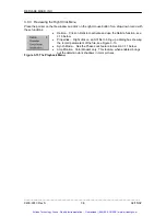
Page 27: ...osite Out connection to a remote monitor or VCR 3 5 The MotionScope Control Functions All controls status and setup values are shown in the application window The video pictures are shown in camera windows or computer file windows The system has five principle functions Live Record Save Load and Playback 3 5 1 The Initial Application Window When the program loads the application window comes up wi...

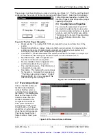
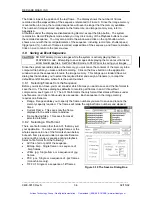
Page 28: ...t to 100 reference Frame 0 is the last frame in the Image Memory A mid range Trigger Point for example 50 would place reference Frame 0 at the middle frame following frames would have positive ascending numbers showing post event images Preceding frames have negative descending numbers and show the pre trigger images Figure 3 2 The Property General Dialog Box To change the Frame 0 reference in a r...

Page 29: ...monitor Refer to Appendix A for the number of pixels and the aspect ratio of the video image Click on the button and click on another rate to change the value See Figure 3 5 3 5 2 3 Extended Record Rate The Extended Record increases the recording time at frame rates up to 500 fps This feature displays an additional range of frame rates in the Record Rate list with the suffix E 60E 125E 250E and 50...

Page 30: ...icture This determines the settings for the host computer monitor see Section 2 3 Max Record Rate Refer to Appendix A to see the record times for your system Memory Installed Refer to Appendix A for performance details for your system Drive and Board version This information is not useful for an operator Description This indicates the current status for the system Normally the message says The Cam...

Page 31: ...ou to select the required folder and assign a filename or accept the default EventN Filename where N is the event number 3 8 1 Selecting Frames from the Sequence Before you click on Save you must consider which frames you want to save and the file format to save them in The Save dialog box defaults to recording all frames in an AVI file without compression see Figure 3 10 The AVI file format is th...

Page 32: ...and the elapsed time ET Click and hold on the Slider and drag it right or left to another frame in the sequence The Frame number and ET windows show the current frame parameters as the Slider moves 3 9 1 Playing from the Image Memory CAUTION DO NOT attempt to save images while the system is actively playing them in PLAYBACK mode Attempting to save images while playing them can result in lost or sc...

Page 33: ...e to bring up a dialog box showing the record parameters of the file see Figure 3 13 Synch Mode See the Phase Lock feature in Section 3 11 below Amplification Color Models only This feature when enabled brings out the details in dark shadows in color pictures Figure 3 13 The Playback Menu _____________________________________________________________________________ 9400 0010 Rev S 3 8 02 15 02 Art...

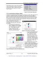
Page 34: ...is shows the following The width and color of the Reticle lines To increase the width increase the line width from 1 to 5 To change the color of the Reticle line click on the Color button and select another color from the range displayed Click Apply to view the color and OK to color the lines Figure 3 15 The Reticle Lines Settings The color of the Reticle Data Set Points Point In and Point Out Of ...

Page 35: ...t over the point of interest on the image Release the mouse button to place the reticle at the desired location See Figure 3 19 Figure 3 18 The Right Click Reticle Menu This places a Set Point at where the reticle lines intersect The color of the marker indicates that this point is on the current frame Refer to paragraph 3 10 1 above Place another set point on the image to enable you to scale or c...

Page 36: ...he distance measured on the subject in the Distance field and click on OK 5 Click on the Reticle button or the mouse right button while pointing in a window to bring up the Reticle dialog box 6 The system calculates the distance between markers Once the system is calibrated it can measure all distances 7 If you go to another frame and place a set point on that frame the system can calculate the ti...

Page 37: ...l Points button 3 10 4 Exporting the Data Points Listing The data points listed in Figure 3 22 are in a form that can be exported to a spreadsheet program like Excel To export the data highlight the points to be exported then press the Export button 3 11 Synchronizing a Video Sequence A MotionScope camera can be synchronized to another MotionScope camera or receive signals from an external source ...

Page 38: ...tomatically increments by one each time you record an event 2 Click on Event Enter notes up to 255 characters about the event 4 2 2 2 Record Rate The button shows the current rate set 1 The default rate is 60 frames per second 2 Click on this button to set a new record rate The button displays the record rates available Extended record rates have an E suffix 3 The 8000 fps record rates show either...

Page 39: ...ollow this procedure to record an event on two or more synchronized cameras Connect the cameras through their Phase Lock BNC connectors located on pigtails on the camera cable Set the same record rate on all cameras Only connect and set the trigger on the Master camera The Slave cameras will follow the Master frame by frame and stop recording when the Master stops recording Since in the Slave s do...

Page 40: ...ttons to view the sequence Click on Live to return to the Live mode 4 6 Viewing the Stored Image CAUTION DO NOT attempt to save images while the system is actively playing them in PLAYBACK mode Attempting to save images while playing them can result in lost or scrambled image files Set PLAYBACK mode to STOP prior to saving your images You can review the image in the Image Memory immediately 1 Set ...

Page 41: ...GE INTENTIONALLY LEFT BLANK _____________________________________________________________________________ 9400 0010 Rev S 4 4 02 15 02 Artisan Technology Group Quality Instrumentation Guaranteed 888 88 SOURCE www artisantg com ...

Page 42: ...creen defaults to saving the complete sequence in an AVI file If you want all of the contents of the image memory click on Save now Go to paragraph 5 2 4 To save the Current Frame or a Range of frames click on the radio button For a Range specify the start and finish frame numbers and whether to save all frames or one frame per interval through the sequence Frame Saving Step such as for example sa...

Page 43: ... of interest and when the target lines are placed accurately release the left button on the newest Set Point location 6 At any time you may clear the last Set Point or clear all Set Points 5 3 3 Calibrating for Distance and Velocity Measurements 1 Go to the subject and physically measure the distance between two points perpendicular to the camera view Set the two points 2 Click on Reticle Calibrat...

Page 44: ...t set correctly Start Settings Control Panel Display Set the resolution to 1024x768 Monochrome systems 256 colors Color systems True Color 24 or 32 bit 8 Wrong software revision level 9 Dirty contacts on the Controller board PCI connector Remove the board and clean the contacts with an appropriate cleaner or a pencil eraser 6 2 3 Waffle Pattern on the Monitor This pattern see Figure 6 1 or black s...

Page 45: ...cable to the Control Display Unit to determine whether the fault is located in the camera head the cable or connectors or in the Controller board Figure 6 2 Video Channel Imbalance NOTE Always replace a camera or camera cable with one of the same version For example a 07 camera must replace an existing 07 camera A 06 camera will not work with that system Check that the Serial Number and Revision L...

Page 46: ...c 4 096 8 2 Sec 8 192 16 4 Sec 1000S 320 x 156 2 048 2 0 Sec 4 096 4 1 Sec 8 192 8 2 Sec MotionScopeÒ 2000 S Monochrome Recording Time Sec Frame Storage Frame Rate Resolution Standard Memory Enhanced Memory Maximum Memory Frames Sec Pixels of Frames Record Time of Frames Record Time of Frames Record Time 50 480 x 420 512 10 2 Sec 1 024 20 5 Sec 2 048 41 0 Sec 50E 240 x 210 2 048 41 0 Sec 4 096 82 ...

Page 47: ...10 2 048 34 2 Sec 4 096 68 3 Sec 8 192 136 5 Sec 125 C 480 x 420 512 4 1 Sec 1 024 8 2 Sec 2 048 16 4 Sec 125E 240 x 210 2 048 16 4 Sec 4 096 32 8 Sec 8 192 65 6 Sec 250 C 480 x 420 512 2 0 Sec 1 024 4 1 Sec 2 048 8 2 Sec 250E 240 x 210 2 048 8 2 Sec 4 096 16 4 Sec 8 192 32 8 Sec 500 C 320 x 280 1 024 2 0 Sec 2 048 4 1 Sec 4 096 8 2 Sec 500E 240 x 210 2 048 4 1 Sec 4 096 8 2 Sec 8 192 16 4 Sec 100...

Page 48: ...on the Camera cable for the Trigger Strobe Data Record Composite Out and Phase Lock In Out Trigger Input 1 0 volt input held to ground by a 2K resistor at the source rising to 5 volts up to 30 volts permitted 2 Contact closed rising to 5 volts when contact opens 3 5 volts falling to 0 volts by a contact closure BNC connector Phase Lock In Out Signal TTL level square wave activated on the rising ed...

Page 49: ...4 00 ms 2 00 ms 3X 6 7 ms 5 60 ms 2 67 ms 1 33 ms 4X 5 0 ms 4 20 ms 2 00 ms 1 00 ms 5X 4 0 ms 3 30 ms 1 65 ms 0 80 ms 10X 2 0 ms 1 70 ms 0 80 ms 0 40 ms 15X 1 3 ms 1 10 ms 0 54 ms 0 27 ms 20X 1 0 ms 0 83 ms 0 40 ms 0 20 ms Shutter Speed 500 1 000 2 000 8000 1X 2 000 ms 0 910 ms 0 410 ms 0 120 ms 2X 1 000 ms 0 500 ms 0 250 ms 0 060 ms 3X 0 665 ms 0 335 ms 0 165 ms 0 040 ms 4X 0 500 ms 0 250 ms 0 12...

Page 50: ...bow 9001 0406 50 mm Lens f 1 4 Cosmicar 9001 0408 C Mount Zoom Lenses 12 5 75 mm Zoom Lens f 1 8 w Macro Toyo 9001 0376 8 48 mm Zoom Lens f 1 2 Cosmicar 9001 0386 Lens Accessories C Mount extension tube set 9002 0001 Nikon F to C Mount Adapter 9002 0023 49 mm Close up Lens Set 1 2 4 Toyo only 9002 0058 52 mm Close up Lens Set 1 2 4 Fujinon only 9002 0055 55 mm Close up Lens Set 1 2 4 Cosmicar only...

Page 51: ...080 BNC to RCA Adapter 9042 0519 Lights and Light Accessories Light Lowell Pro P1 10 9003 0037 Bulb GCA 120V 250W 9003 0039 Set of barn doors for Lowell light IP20 9003 0040 Bogen light stand 3373 9003 0038 Lowell Light Kit 1900 0002 Cart Cart 4 Wheel for MotionScope S Series Monitor Video Recorder Cables and Accessories 9018 0079 Cases Carrying Case for MotionScope and System Accessories 9033 003...

Page 52: ...quipment Have surplus equipment taking up shelf space We ll give it a new home Learn more Visit us at artisantg com for more info on price quotes drivers technical specifications manuals and documentation Artisan Scientific Corporation dba Artisan Technology Group is not an affiliate representative or authorized distributor for any manufacturer listed herein We re here to make your life easier How...

Reviews: