Motion
Meter
High Speed Video Camera
_____________________________________________________________________________
9400-0024 Rev. G
3-1
OPERATOR'S INSTRUCTIONS
3 UNPACKING AND CONNECTING THE
Motion
Meter CAMERA
3.1 Unpacking the Motion
Meter
Camera
3.1.1
List of Equipment
Check that you have the following items in the
Motion
Meter package.
•
Camera.
•
AC power adapter with cord and power switch.
•
Carrying Strap.
•
Operator’s Manual.
•
Lens (optional).
3.1.2
Connecting the External Options
This section gives details of the connections and electrical specifications for the Trigger, Strobe,
Event Marker, Video Out and Phase Lock options.
3.1.3
Video Out
The Video Out BNC connector supplies a video signal to an external monitor, VCR or computer.
A computer must have a video capture board to receive and store a video sequence. The camera
outputs NTSC (30 fps) or PAL (25) standard. Use the Settings menu to change the video
standard.
3.1.4
The Event Marker Input
The Event Marker input to
the Digital In connector
shows a white square
when the input is +3.3
volts. A contact closure
to ground turns the
marker black. Select this
input using the Settings
menu.
Figure 3-1 The Event Marker Input Circuits.
There are two types of input that may be applied to the Event Marker inputs, see Figure 3-1:
a) A TTL or CMOS-compatible logic signal or other ground-based logic up to +3.3 volts.
b) A dry-contact closure between open and ground.
3.1.5
The Strobe Output
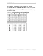
The Strobe signal is a positive-going pulse from the Digital Out that rises when the shutter opens
and falls when the shutter closes. See Figure 3-2. The Strobe signal is enabled when selected in
the Settings menu. The
length of the pulse depends
on the record rate set
(frames per second) and the
shutter setting (1X - 20X,
where X is the record rate).
Refer to Appendix C.
Figure 3-2 The Strobe Circuits.

