REDLAKE MASD, INC.
_____________________________________________________________________________
9400-0024 Rev G
3-2
05/15/01
3.1.6
The Trigger Input
The Trigger input is always enabled in Record mode. The Trigger circuit supplies a +3.3-volt
level to the connector by way of a 10K pull-up resistor. The camera monitors the Trigger input
and detects when a trigger signal is received from an external source. A trigger signal detected
when the camera is recording stops the record sequence at a point determined by the trigger
point setting.
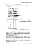
There are three types of signal that may be supplied to the Trigger circuit to stop a record
sequence, see Figure 3-3.
1. The signal input is held at +3.3 volts. A contact closure to ground caused by an event pulls
the input to 0 volts to stop recording. This presents a falling signal edge to the trigger input.
You must set the arrow in the Trigger menu down.
2. A contact closure holds the input to 0 volts. The trigger opens the contacts causing the input
to rise to +3.3 volts. This presents a rising signal edge to the trigger input and you must set
the triangle in the Trigger menu up.
3. A TTL- or CMOS-compatible logic signal, or other ground-based logic with a maximum of 2K
ohms holds the Trigger
input at 0 volts. The
Trigger signal allows the
Trigger input to go to
+3.3 volts to stop
recording. This signal
can go as high as +30
volts. You must set the
arrow in the menu up.
Figure 3-3 Trigger Input
Circuits.
3.1.7
The Phase-Lock Input and Output
1. Determine which camera will be the master and generate the sync pulses. All other cameras
are slaves and receive the sync pulse from the master. See Figure 1-6.
2. At the master camera, connect a BNC connector and cable from the PHASE LOCK OUT
connector.
3. Select the Settings menu for the Master unit. In the Master/Slave line, select Master.
4.
Series Connection.
Connect the cable from Step 2 to the PHASE LOCK IN connector on the
first slave unit. In any downstream camera, connect a BNC connector and cable from the
PHASE LOCK OUT from this slave to the PHASE LOCK IN of the next slave unit.
5.
Parallel Connection.
Install a tee to the cable installed in Step 2. Connect the tee to the
Phase Lock IN connector of the Slave, and install cables and tees to all downstream Slaves.
6. Select the Settings menu on all Slave units. In the Master/Slave line, select Slave.
7. The Event marker is only available when the camera is set to Master. A camera in Slave
mode cannot show an event marker.


