background image


AN-30 System User Manual 


TABLE OF CONTENTS 


1.


Getting Started .......................................................................................................... 8


1.1.


How To Use This Manual .................................................................................. 8


1.2.


AN-30 System Overview ................................................................................... 8


1.3.


TDM over Wireless Theory of Operation........................................................... 9


2.


Important Safety Information................................................................................... 10


3.


Important Service Information ................................................................................. 12


4.


Unpacking the AN-30 System ................................................................................. 13


5.


The AN-30 Terminal at a Glance............................................................................. 14


5.1.


The AN-30 System’s T-58 Transceiver / Antenna at a Glance ....................... 18


6.


AN-30 System Installation....................................................................................... 19


6.1.


General Site Survey ........................................................................................ 20


6.2.


Installing The Antenna..................................................................................... 21


6.3.


Running The IF Cable ..................................................................................... 22


6.4.


Installing The Terminal .................................................................................... 23


6.5.


Aligning The Antenna ...................................................................................... 25


7.


System Configuration and Operation Via The Console Port ................................... 27


8.


System Configuration and Operation Via Telnet ..................................................... 28


9.


AN-30 CLI (Command Line Interface) for Wireless and Ethernet ........................... 30


9.1.


CLI General Commands.................................................................................. 30


9.2.


CLI System Configuration Commands ............................................................ 31


9.3.


CLI General Status Information Commands.................................................... 35


9.4.


Upload Software.............................................................................................. 38


9.5.


System Password............................................................................................ 39


9.6.


AN-30 Options................................................................................................. 39


9.7.


System Logs.................................................................................................... 40


10.


AN-30 CLI (Command Line Interface) for the TDM card..................................... 43


10.1.


DS0 Bundles................................................................................................ 43


10.2.


Command Line Interface ............................................................................. 44


10.3.


Quick Setup................................................................................................. 45


10.4.


Configuration ............................................................................................... 46


10.5.


Control commands ...................................................................................... 46


10.6.


General configuration commands................................................................ 48


10.7.


Serial interface configuration commands .................................................... 52


10.8.


DS0 Bundle configuration commands ......................................................... 53


10.9. ............................................................................................................................ 56


10.10.


Sample Setup Scripts .................................................................................. 57


10.11.


Statistics commands.................................................................................... 59


10.11.1.


Ethernet properties and statistics ........................................................ 59


10.11.2.


TDM properties and statistics .............................................................. 60


11.


Broadband Fixed Wireless Primer....................................................................... 62


11.1.


Who Can Benefit From The AN-30 System?............................................... 62


11.2.


The AN-30 Advantage ................................................................................. 64


11.3.


Wireless Facts ............................................................................................. 66


11.3.1.


The Link Budget Tool .............................................................................. 66


11.4.


Deployment Scenarios ................................................................................ 72


11.4.1.


Co-located Deployments ......................................................................... 72


11.4.2.


Adjacent Area Deployments .................................................................... 72


12.


Appendix ............................................................................................................. 74


Page 4 of 80 

Redline Communications


…..solving the first mile challenge


Summary of Contents for AN-30 System

Page 1: ...AN 30 System User Manual AN 30 System User Manual AN 30 System User Manual Manual 70 00019 00 Rev 3 ...

Page 2: ...and troubleshoot the Redline AN 30 Broadband Fixed Wireless BFW system Every effort has been made to ensure the accuracy of the material provided herein however Redline assumes no responsibility regarding the use of the material Additionally Redline makes no representations or warranties either expressed or implied regarding the contents of this product Redline Communications shall not be liable f...

Page 3: ...of a device which is marketed for use by the general public or is intended to be used in the home 3 Intentional or unintentional changes or modifications not expressly approved by the party responsible for compliance must not be made Any such modifications could void the user s authority to operate the equipment and will void the manufacturer s warranty Contact Information Redline Communications I...

Page 4: ...nfiguration Commands 31 9 3 CLI General Status Information Commands 35 9 4 Upload Software 38 9 5 System Password 39 9 6 AN 30 Options 39 9 7 System Logs 40 10 AN 30 CLI Command Line Interface for the TDM card 43 10 1 DS0 Bundles 43 10 2 Command Line Interface 44 10 3 Quick Setup 45 10 4 Configuration 46 10 5 Control commands 46 10 6 General configuration commands 48 10 7 Serial interface configur...

Page 5: ...User Manual 12 1 Appendix 1 Glossary Of Terms 74 12 2 Appendix 2 AN 30 Support For TDM explained 76 12 3 Appendix 3 AN 30 System Specifications 77 Page 5 of 80 Redline Communications solving the first mile challenge ...

Page 6: ... Table 4 Max Operational Power Per Channel in dBm vs Modulation 33 Table 5 RF Status Error Codes 36 Table 6 E1 Framed Configuration Script 57 Table 7 T1 Framed Configuration Script 58 Table 8 Modulation Scheme vs Data Rate 67 Table 9 Availability Versus Outage Time 69 Table 10 Radar Horizon Ranges For Different Terminal Heights H1 and H2 71 Page 6 of 80 Redline Communications solving the first mil...

Page 7: ...0 Terminal LAN Ethernet Port Pinout 25 Figure 13 Aligning The Antenna Vertical Mount 25 Figure 14 System Logs Screen 40 Figure 15 Typical PTP single hop configuration 43 Figure 16 Typical PTP multi hop configuration 44 Figure 17 Wireless Extension for Carriers 62 Figure 18 Wireless Solution For ISPs 63 Figure 19 Wireless Solution For Enterprise 64 Figure 20 Fresnel Zone Obstruction 68 Figure 21 Fr...

Page 8: ...User Manual will also help with the following Understanding Fixed Wireless Systems Referencing AN 30 System Specifications Troubleshooting the System 1 2 AN 30 System Overview The AN 30 is a wireless transport system providing simultaneous interfacing for legacy TDM and data traffic Its architecture makes it an ideal platform to facilitate the migration from a TDM based telecom infrastructure to a...

Page 9: ...orks and can be introduced by the AN 30 during packet processing and transmision of simultaneous TDM and data traffic streams In order to insure proper timing of the reconstructed traffic the remote AN 30 employs a jitter buffer that is user defined between 5 and 300 msec The jitter buffer is used to compensate for any delay variation that may occur during transport of the ethernet encapsulated tr...

Page 10: ...nnect the power before cleaning 10 Protect the unit by disconnecting the power if it is not used for long periods of time 11 Locate the AN 30 terminal on a stable horizontal surface or mount it securely in a 19 Telco rack 12 The T 58 Transceiver unit must not be located near power lines or other electrical power circuits 13 The T 58 Transceiver must be properly grounded to protect against power su...

Page 11: ...mean danger Bodily injury may result if you are not aware of the safety hazards involved in working with electrical equipment and radio transmitters Familiarize yourself with standard safety practices before continuing Electro Magnetic Radiation High Voltage Page 11 of 80 Redline Communications solving the first mile challenge ...

Page 12: ...AN 30 terminal has been exposed to rain c The product has been dropped or the housing is damaged 3 Locate the serial number of the AN 30 Terminal Antenna and T 58 Transceiver and record these on your registration card for future reference Use the space below to affix serial number stickers Also record the MAC address located on the back of the AN 30 Terminal Product Information AN 30 Terminal SN _...

Page 13: ... unit AN 30 Radio outdoor unit T 58 Transceiver Antenna Antenna Mounting Bracket Power Cord and outdoor IF Cable 100 ft 30 5 m User Manual AN 30 Terminal AN 30 Radio Power IF Cables Vertical Mount User Manual Figure 1 The AN 30 System Out Of The Box A complete list of items included in the system is available on the packing list included with the system Page 13 of 80 Redline Communications solving...

Page 14: ...heir normal state A System Status Indicators The System portion of the front panel features a recessed reset switch and two LEDs Pwr and Fault as shown in the figure below Figure 2 Front Panel System Reset The system can be manually hard reset by depressing the Reset button recessed in the front panel The reset button is used to reactivate the terminal in the event that it is functioning improperl...

Page 15: ...LED will flash when the Local Area Network LAN connection is established and there is traffic 100 The 100 LED lights solid green when the Ethernet port is operating at 100 Mb s The LED will not illuminate if the port is operating in 10 Mb s mode The Ethernet port automatically selects the speed through auto negotiation with either the host computer server or router switch FD The FD LED is used to ...

Page 16: ...te in band management Optional license keys are available to activate access at higher speeds Warning Exceeding the basic access rate of this port may impact the performance on the TDM interfaces E The TDM Interface The TDM interface includes four RJ48 BNC E1 T1 ports which are used to connect the AN 30 terminal to either a PBX or to another E1 T1 device Note that different cables are required for...

Page 17: ... the following table ALARM Alarm LED Amber Sync LED Green AIS LFA Off Blink AIS RAI Flashes Off RAI LFA Flashes Flashes LOS Loss of Signal LFA Loss of Frame Alignment AIS Alarm Indication Signal RAI Remote Alarm Indication Page 17 of 80 Redline Communications solving the first mile challenge ...

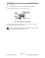
Page 18: ...58 Transceiver Mount Bracket Pole Figure 6 AN 30 Radio With Vertical Mount The vertical mount bracket can accommodate 1 to 4 4 45 cm 11 45 cm OD masts found on many commercial tower installations Before connecting the AN 30 system it is important to review the safety tips provided at the beginning of this manual Page 18 of 80 Redline Communications solving the first mile challenge ...

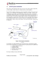
Page 19: ...e T 58 Transceiver located outdoors and carries the transmitted and received signal DC power for the AN 30 radio as well as control and reference signals Note that the provided IF cable is meant for exterior use and should be used for only minimal interior runs to connect to the terminal Also note that the BNC connectors are for future use Figure 7 AN 30 System Installation AC shown The terminal i...

Page 20: ...rawings of the building are up to date and accurate It may also be possible for the IF cable to be installed on the outside of the building leading to the antenna location on the roof of the building Identify the best path for the link For maximum performance it is recommended to mount the antenna in a location where there is line of sight to the remote terminal If possible the antenna should be p...

Page 21: ...Installing The Antenna Once the site survey has been completed and the exact location for the antenna identified the next step is to assemble and mount the radio onto either a building structure pole or tower Note there is an arrow on the back of the antenna which must point in the same direction for both the local and remote systems to ensure proper polarization when the antenna is deployed see F...

Page 22: ...ngth of the appropriate cable be used coupling the provided 100 foot cable to another length will result in increased attenuation Refer to the cable requirements in the Specifications section at the end of this manual Note If male F type crimp connectors are used with custom cables the cable s core conductor diameter must be no larger than 1mm 042 inches or longer than 1cm 0 38 inches to avoid dam...

Page 23: ...uitable arrestor may be purchased through any of Redline s system integrators Note that performance may be affected by the use of other arrestors 4 Connect the IF cable to the F type female connector located on the back of the terminal The connector should be tightened finger tight and then tightened an additional 1 8 of a turn 6 4 Installing The Terminal Once the AN 30 terminal and the radio are ...

Page 24: ...e is required to complete the connection Figure 11 AN 30 Terminal Connected To Host Computer To help you establish other implementations that are not addressed in this manual Figure 12 provides an illustration of the pinout for the AN 30 terminal LAN interface Warning do not connect a telephone cable to the AN 30 LAN interface as this will damage the terminal Page 24 of 80 Redline Communications s...

Page 25: ...elevation planes Elevation alignment is accomplished by loosening the two bolts attached to the mounting bracket as shown in Figure 13 below and angling the antenna so it is aligned towards the remote terminal The azimuth alignment is accomplished by loosening the bolts on the antenna bracket and rotating the antenna until alignment is achieved For basic tuning using actual signal strength an alig...

Page 26: ...ray PMP PTP 485002 23 0 Directional planar array PMP PTP 485024 21 0 Directional flat panel PMP PTP 484027 14 0 Directional flat panel PMP PTP 484026 15 0 Omni Directional flat panel PMP 484025 14 0 Omni Directional flat panel PMP SP4 5 2 34 8 Directional parabolic PMP PTP SP3 5 2 31 2 Directional parabolic PMP PTP SP2 5 2 29 0 Directional parabolic PMP PTP SP1 5 2 22 5 Directional parabolic PMP P...

Page 27: ...emale female Set the PC Terminal to emulate a VT 52 or VT 100 terminal using the following port settings Bits Per Second 9600 Data Bits 8 Parity None Stop Bits 1 Flow Control Hardware Hit the Enter key the AN 30 prompt will appear The diagram below shows the 9 PIN D SUB male connector pinout at the AN 30 Terminal Pin Name RS232 V 24 Description 1 CD CF 109 Carrier Detect 2 RXD BB 104 Receive Data ...

Page 28: ...ands Type help for a list of general commands The AN 30 is factory set with two login accounts Administrator and User Logging in under the administrator account allows all privileges Logging in under the user account restricts the privileges to executing show and get operations only The factory set default values for each account s username and password are given below Table 2 Factory Defaults For...

Page 29: ...55V 60 17 17 0 Directional sector PMP 5 4 19 0 36 SEC 55V 90 16 16 0 Directional sector PMP 5 4 20 0 36 MPR58031 PTNF 31 0 Directional parabolic PMP 5 4 5 0 36 MPR58029 PTNF 29 0 Directional parabolic PMP 5 4 7 0 36 TDJ 5818AM 60 18 0 Directional sector PMP 5 4 18 0 36 TDJ 5816AM 90 16 0 Directional sector PMP 5 4 20 0 36 486001 28 0 Directional planar array PTP 5 4 25 3 No limit 485002 23 0 Direc...

Page 30: ...rameter value Get parameter name displays the value for a status parameter For configuration parameters use Set command login Allows login under a different username and password logout Disconnects user from the terminal passwd Change Password passwd username newpassword Change password for user reboot Reboot time in seconds Reboots the terminal resetstats Reset Statistics Resets all statistics sa...

Page 31: ...racters in length The default name for the system from the factory is set to WEB01 The name remains with the system even during power off states until the operator re types a new name using this menu field sysdetails System Details Specifies the location of the unit telephone number and or contact information of the network administrator Can be up to 20 characters in length ipaddr IP address This ...

Page 32: ... 2 AN 30 Support For TDM explained telnet Telnet Enable Telnet is used to connect to remote devices usually via Telnet port 23 Once a Telnet connection is established it is possible to log in using the admin or user user id and set the parameters of the unit using the CLI telnetport Telnet Port The default Telnet port is 23 The port can be changed to any other number between 23 and 65 000 excludin...

Page 33: ...el Frequency 1 5735 MHz 1A 5745 MHz 2 5755 MHz 2A 5765 MHz 3 5775 MHz 3A 5785 MHz 4 5795 MHz 4A 5805 MHz 5 5815 MHz To avoid interference two PTP links operating in the same physical location co located or within close proximity must be separated by at least one channel i e the gap between channels must be 20 MHz or more e g channels 2 and 3 Refer to Section 10 4 for further information regarding ...

Page 34: ...t the Uncoded Burst Rate and the Modulation Reduction Level see below To operate in manual mode first sample the link with Adaptive Modulation enabled then switch to manual mode setting the modulation scheme up to 2 levels lower than that achieved using adaptive modulation Note In some countries outside of North America the Maximum Operational Power Per Channel with a given antenna is limited in a...

Page 35: ...ation Allows testing of the current settings for five minutes after which the system reverts to the previously saved settings To make settings permanent click Save reboot System Reset Resets all statistics and reboots the terminal 8 3 CLI General Status Information Commands The following is a brief description of each field of the CLI General Status Information sysname System Name Identifies the l...

Page 36: ...D rffreq RF Channel Frequency Specifies the center frequency of the channel in use Tx Power Specifies the actual current transmit power level cableattn Cable Attenuation Indicates the attenuation of the signal over the IF cable rfstatus RF Status Error Code An error code from 0 31 indicating the condition of the RF components within the AN 30 terminal and T 58 Transceiver See the RF Status Error C...

Page 37: ... the AN 30 terminal If the Low DC Voltage At Radio error is also indicated see below check the IF cable and connectors If the Low DC Voltage At Radio error is not indicated the T 58 Transceiver will require servicing Low DC Voltage At Radio Input The DC voltage at the transceiver carried by the IF cable from the AN 30 terminal is lower than the required 24VDC Check the IF cable and connectors The ...

Page 38: ...of wireless packets retransmitted over the air by the local terminal The retransmission scheme is based on the Automatic Repeat Request ARQ algorithm that detects when packets are lost and makes a request to the MAC scheduler to repeat transmission of the lost packets wtxpktd Tx Packets Discarded Indicates the total number of transmitted wireless packets discarded by the remote terminal due to deg...

Page 39: ...nal will reject the new software load and provide a warning that the upgrade was unsuccessful In this case the operator will need to repeat the upload process 8 5 System Password The factory default password for the system is admin for the administrator s ID and user for the user s ID To change the password use the CLI command passwd username newpassword using any alphanumeric combination for the ...

Page 40: ...ave occurred 108 Version control loaded successfully 103 Parameters saved successfully 100 Parameters loaded successfully 101 Firmware configuration OK 106 Firmware programmed OK 111 SNMP configuration loaded successfully 103 Parameters saved successfully 105 Password changed successfully Figure 14 System Logs Screen The show log CLI command can be use in order to display the log file The logs wil...

Page 41: ...software to the AN 30 terminal during the Upgrade process failed Likely cause is disconnected or faulty cable 210 Error TFTP unknown message The TFTP client received an unknown message In this case repeat the upgrade process 211 Error while writing flash While writing the new software into AN 30 terminal flash memory an unexpected error occurred Try to repeat the process and if the error persist c...

Page 42: ...et the terminal If the problem persists contact customer support 225 Error while loading SNMP configuration EEPROM memory was corrupted and the SNMP configuration couldn t be loaded Default SNMP configuration was loaded 226 Error while saving SNMP configuration SNMP configuration saving process wasn t successfully Try again If the problem persists contact customer support Page 42 of 80 Redline Com...

Page 43: ...and running contiguously from 1 to a maximum of 24 1 timeslots for T1 links and a maximum of 32 timeslots for E1 links An AN 30 can support a maximum of 4 DS0 Bundles Figure 15 illustrates a typical single hop PTP configuration back hauling 2 full rate T1 E1 lines in a mobility application All traffic is terminating at a the same endpoints and therefore requires definition of one DS0 bundle for ea...

Page 44: ...eration a set operation and a show operation The tdm get operation is used to retrieve the specified parameter value from a running configuration of an active system The tdm set operation is used to modify the specified parameter value in the temporary configuration The tdm show category operation is used to list all parameter values of the specified command category for either the running configu...

Page 45: ...f packetlen When setting up two AN 30s to form a wireless link the following steps must be completed in the sequence shown below Local Remote Define General Parameters Local Remote Define Serial Interface Parameters Local Remote Define Bundle Parameters ipaddr ipmask gateway vlandata vlanvoice clock coding framing Lbo T1 only tsbegin tsnum jitterbuf packetlen Local AN 30 Bundle Parameters destbund...

Page 46: ...ol commands are used to manipulate the contents of each of the configuration images as well as to save and activate a specific configuration There are 4 control commands tdm start tdm exit tdm save tdm copy tdm start no params This command synchronizes the temporary configuration with the running configuration Before making any changes to the temporary configuration you must first issue the tdm st...

Page 47: ...he modified temporary configuration is checked If valid config is saved to running config and software is restarted If configuration is not valid i e serial interface pointed by syncon is disabled an error code is returned containing 3 fields LEVEL NUMBER ERROR_ID and save command is ignored The meaning of the error code bytes is presented in the following Level Definition 0 General Level 1 Serial...

Page 48: ...ies the current running configuration into the Startup configuration A running configuration is stored in volatile memory and will be lost in the event of a system reset Therefore once you are satisfied with a new configuration the tdm copy command must be issued to store the new configuration into the Startup Image This is the only way to permanently save an operating configuration In order to in...

Page 49: ... operation hostname params HOST The hostname of the T1 E1 module ipaddr params IP address in format a b c d The IP address of the T1 E1 module The TDM module in the AN 30 is uniquely identified by its IP address The IP address is used with the destip command to direct TDM traffic to a specific AN 30 end point By uniquely addressing the TDM module within the AN 30 it is possible to relay traffic th...

Page 50: ...gnal of a serial interface port Adaptive clocking should be selected at the remote side of the wireless link to have the AN 30 continuously adapt its T1 E1 transmit clock In the case of adaptive clocking the AN 30 uses its internal clocking reference and adapts its transmit clock based on information extracted from the fill level of the jitter buffer for the serial interface port specified with th...

Page 51: ...the line type on the T1 E1 module if permitted by the option key LINE_TYPE Definition 0 T1 line 1 E1 line softver no params This command is used only with a get operation Represents the coded software version fanstate no params This command will return 1 if the fan is ON working and return 0 if the fan is OFF not working Show Operations The show operation is tdm showgen tdm showgen params CONFIG T...

Page 52: ...y after the tdm save command is successfully executed In the following commands the serial interface number SN parameter must be a valid serial interface number i e for 4 T1 E1 valid values are 1 2 3 and 4 otherwise the command will return non ack The commands for serial interface configuration are coding framing lbo The second parameter for each command is valid only if used with the set operatio...

Page 53: ...0 running config 1 startup config 9 8 DS0 Bundle configuration commands A DS0 bundle is a logical mapping of a number of timeslots from the same physical T1 E1 port The starting timeslot selected ts_begin is ts_begin 0 if the line is unframed In this case the number of selected ts must be 32 for E1 or 24 1 for T1 1 ts_begin 31 24 for T1 and tsnumber 32 ts_begin 24 1 ts_begin for T1 for framed In t...

Page 54: ...commands to execute successfully The following valid values for BN result Serial Interface Number Minimum BN Value Maximum BN Value 1 1 32 2 33 64 3 65 96 4 97 128 The bundle configuration commands are tsbegin tsnum destbundle destip jitterbuf packetlen Command Descriptions A bundle is automatically created through the definition of its associated parameters The commands tsbegin and tsnum are used...

Page 55: ...module This is the IP address that was assigned to the TDM module using the general command ipaddr jitterbuf params BN JBLEN This command specifies the jitter buffer length in milliseconds for the specified bundle BN Allowed values for JBLEN 5 300ms The jitter buffer is used to compensate for any delay variation that may occur during transport of the ethernet encapsulated traffic For delay sensiti...

Page 56: ...he specified BN from either the running or startup config The default configuration selected is running config CFG Definition 0 running config 1 startup config Other commands Other commands are tdm delbundle tdm delbundle params BN This command is used to delete the settings of bundle number BN 9 9 Page 56 of 80 Redline Communications solving the first mile challenge ...

Page 57: ...tdm set framing 3 2 tdm set coding 4 2 tdm set framing 4 2 DS0 Bundle tdm set tsbegin 1 1 tdm set tsnum 1 31 tdm set destbundle 1 1 tdm set destip 1 192 168 100 199 tdm set jitterbuf 1 60 tdm set packetlen 1 128 tdm set tsbegin 33 1 tdm set tsnum 33 31 tdm set destbundle 33 33 tdm set destip 33 192 168 100 199 tdm set jitterbuf 33 60 tdm set packetlen 33 128 tdm set tsbegin 65 1 tdm set tsnum 65 3...

Page 58: ...dm set ipmask 255 255 255 0 tdm set vlandata 2 tdm set vlanvoice 3 tdm set clock 0 tdm set syncon 1 tdm set idlecode 255 tdm set line 0 Serial Interface tdm set coding 1 0 tdm set framing 1 0 tdm set coding 2 0 tdm set framing 2 0 tdm set coding 3 0 tdm set framing 3 0 tdm set coding 4 0 tdm set framing 4 0 tdm set coding 1 0 tdm set framing 1 0 tdm set coding 2 0 tdm set framing 2 0 tdm set codin...

Page 59: ...egin 65 1 tdm set tsnum 65 24 tdm set destbundle 65 65 tdm set destip 65 192 168 100 192 tdm set jitterbuf 65 60 tdm set packetlen 65 128 tdm set tsbegin 97 1 tdm set tsnum 97 24 tdm set destbundle 97 97 tdm set destip 97 192 168 100 192 tdm set jitterbuf 97 60 tdm set packetlen 97 128 Control tdm save tdm save 9 11 Statistics commands 9 11 1 Ethernet properties and statistics tdm get ethprate no ...

Page 60: ...turns single collisions tdm ethsmcol no params Returns multiple collisions tdm get ethstdef no params Returns transmission deffered tdm get ethslcol no params Returns late collisions 9 11 2 TDM properties and statistics All commands return non ack if the parameter SN is not valid 4 A value of SN 4 is invalid tdm get tdmslos params SN Returns loss of signal tdm get tdmslfa params SN Returns loss of...

Page 61: ...nd will return non ack STAT Definition 0 reserved for all statistics not yet implemented 1 4 TDM statistics on serial interface 1 4 5 32 reserved for many serial interfaces 33 Ethernet Statistics 34 Ethernet Properties 35 Debug Statistics tdm resetstat params STAT This command resets the module specific statistics selected by STAT If STAT is not valid the command will return non ack STAT Definitio...

Page 62: ...aphical area they are faced with the challenges of reaching outlying regions suffering from poor to no service The ILEC is usually compelled to provide an expensive solution using a series of PTP radio links with low throughput e g T1 and costly license fees and network interfaces including T1 multiplexers The AN 30 system provides a cost effective alternative by connecting a remote site from the ...

Page 63: ...fect for ISPs looking to provide cost effective broadband solutions to demanding business customers including Small Office Home Office SOHO and Small to Medium sized Enterprises SME located just outside of the downtown core where there is a lack of infrastructure High speed leased lines are expensive and hard to obtain especially from local telephone companies Wireless access provides a reliable q...

Page 64: ...t within the education system today with BFW systems serving as an important enabler in bringing Internet content to the student body Fixed wireless systems such as the AN 30 provide a cost effective means of creating a backbone for connecting existing and new campus buildings to the educational infrastructure to support distance learning and two way interactive training 10 2 The AN 30 Advantage T...

Page 65: ...ow Beam Width Narrow antenna beams reduce considerably the probability of interference entering the system In addition to the anti interference features described above the AN 30 system also holds several other competitive advantages High Data Rates High Bandwidth Efficiency Long Reach and Wide Coverage Higher Power Efficiency Over the Air Security Support For TDM Applications By supporting 802 1p...

Page 66: ...ons interference issues and radar horizon considerations 10 3 1 The Link Budget Tool Redline has developed a Link Budget Tool to help characterize the range performance of the AN 30 system for LOS OLOS optical line of sight and NLOS conditions and various system parameters The Link Budget Tool can be obtained by contacting your Redline certified partner or system integrator Note the tool provides ...

Page 67: ...ce loss attenuation in dB and Grx is the receive antenna gain in dB The FSL value is dependent on the range between the two terminals the type of terrain over which the link is deployed and whether or not the link is operating line of sight LOS optical line of sight OLOS or non LOS NLOS The LOS FSL calculation is well understood and easy to calculate and relies on the fact there is absolutely no o...

Page 68: ...lculation Specific FSL formulas are required to deal with this NLOS phenomenon There are many NLOS calculations available from established institutions including the Institute of Electrical and Electronics Engineers IEEE and International Telecommunications Union ITU who are chartered with developing standardized calculations The Redline Link Budget Tool is built upon these formulas however it is ...

Page 69: ...mined by the availability one desires Availability is defined as the amount of time expressed in per year that a link properly detects the signal Properly in this case is a BER that is less than 10 9 The table below describes the outage period per year that corresponds to the different availability values Table 9 Availability Versus Outage Time Availability Outage Period Per Year 99 9 8 8 hours 99...

Page 70: ... 3 4 code rating providing a net burst throughput of 54 Megabits per second Mbps This provides an average throughput of 43 Mbps to the Ethernet port The calculation is performed for LOS however the graph shown in Figure 23 below also covers the OLOS and NLOS conditions Figure 22 Link Budget For 64 QAM Code Rate A fade margin graph for this link budget is given in Figure 23 below for four condition...

Page 71: ... h h km where h1 is the height of terminal 1 m h2 is the height of terminal 2 m The table below specifies the horizon distance km that can be achieved for different terminal heights ranging from 10 to 70 m above mean terrain level Table 10 Radar Horizon Ranges For Different Terminal Heights H1 and H2 H2 10 20 30 40 50 60 70 10 25 9 31 3 35 4 38 9 42 0 44 7 47 3 20 31 3 36 7 40 8 44 3 47 3 50 1 52 ...

Page 72: ...ystem as shown in Figure 24 C is the desired channel while I is the interferer Frequency Mhz Power dB Figure 24 Adjacent Channel Interference 10 4 2 Adjacent Area Deployments During the installation process it is important to ensure there is no potential for interference from other systems deployed in adjacent areas Figure 25 presents a simple deployment configuration to illustrate the potential i...

Page 73: ...AN 30 System User Manual Figure 25 Deployment Scenarios Page 73 of 80 Redline Communications solving the first mile challenge ...

Page 74: ...rmat until reformatted with a decryption key Ethernet A LAN architecture using a bus or star topology FD Full Duplex Refers to the transmission of data in two directions simultaneously i e a telephone FWA Fixed Wireless Access Gain The ratio of the output amplitude of a signal to the input amplitude of a signal Typically expressed in decibels dB Gateway A network point that acts as an entrance to ...

Page 75: ...a specific way for transmission The three principal elements of a packet include the header the text and the trailer error detection and correction bits PHY Physical Layer Provides for the transmission of data through a communications channel by defining the electrical mechanical and procedural specifications PTP Point to Point QAM Quadrature Amplitude Modulation QPSK Quadrature Phase Shift Keying...

Page 76: ...uring the flow controlled period only flow control packets can be transmitted between across the Ethernet link The AN 30 uses this mechanism internally transmitting pause control frames as required based on the availability of its own internal resources including buffers transmit queues and receive queues Since Ethernet traffic typically runs at 100 Mbps it can easily exceed the maximum capacity o...

Page 77: ...100 feet at 250 C RG11 5 dB 30m 100 feet at 250 C Multiplexed IF DC power control Tx Rx AGC APC Network Attributes Transparent bridge DHCP passthrough VLAN passthrough 802 3x Ethernet flow control 802 1p Network traffic prioritization Modulation Modulation Options bi directional BPSK QPSK 16 QAM 64 QAM Over The Air Encryption Proprietary 64 bit encryption Coding Rates 1 2 3 4 and 2 3 MAC Point to ...

Page 78: ...anced 75 Ohm BNC Balanced 100 Ohm Jitter ITU T G 823 Per AT T TR 62411 ITU T G 824 Clocking Adaptive Loopback Internal Adaptive Loopback Internal Line Protection ITU T K 20 K 21 Bell Core GR 1089 AN 30 Physical Specifications Power Requirements Single Dual 110 220 240 VAC auto sensing 50 60 Hz 39W maximum Single Dual 48 VDC 39W maximum Operating Temperature Range AN 50 Terminal Operating Condition...

Page 79: ...AN 30 System User Manual MTI part No MT 485002 Page 79 of 80 Redline Communications solving the first mile challenge ...

Page 80: ...AN 30 System User Manual Page 80 of 80 Redline Communications solving the first mile challenge 302 Town Centre Blvd Markham Ontario Canada L3R 08E www redlinecommunications com ...

Reviews: