background image

US-12

BCZ3050S/T/SW

8. Operation

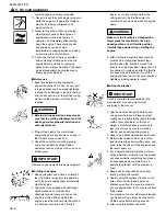
STARTING ENGINE

The cutting head will start rotating
upon the engine starts.

1. Rest the unit on a flat, firm place. Keep

the cutting head off the ground and
clear of surrounding objects as it will
start rotating upon starting of the
engine.

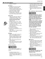
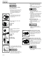
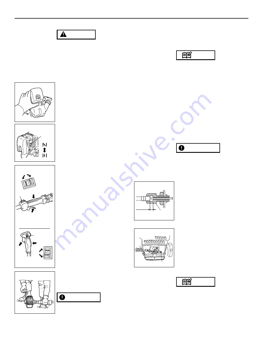
2. Push the primer pump several times

until overflown fuel flows out in the
clear tube. (OP1)

3. Move the choke lever to the closed

position. (OP2)

(1) choke lever 
(2) close 
(3) open 

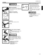
4. Set the stop switch to the "RUN"

position.
Place the unit on a flat, firm place.
Keep the cutting head clear of
everything around it. (OP3)

(1) stop switch 
(2) RUN
(3) STOP

(a) lockout lever 
(b) throttle trigger

5. Firmly grasp 

(a)

and 

(b)

with left hand,

pull the starter knob quickly until engine
fires. (OP4)

• Avoid pulling the rope to its end or

returning it by releasing the knob. Such
actions can cause starter failures.

IMPORTANT

WARNING

OP1

(2)

(3)

(1)

OP2

(1)

(1)

(2)

(3)

(3)

(a)

(a)

(b)

(b)

(2)

BCZ3050S
BCZ3050TS

BCZ3050SW

OP3

OP4

6. Move the choke lever downward to

open the choke. And restart engine.
(OP2)

7. Allow the engine to warm up for several

minutes before starting operation.

1. When restarting the engine

immediately after stopping it, leave the
choke open.

2. Overchoking can make the engine hard

to start due to excess fuel. When the
engine failed to start after several
attempts, open the choke and repeat
pulling the rope, or remove the spark
plug and dry it.

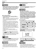
STOPPING ENGINE (OP3)

1. Release the throttle lever and run the

engine for a half minute.

2. Shift the stop switch to the "STOP"

position.

• Except for an emergency, avoid

stopping the engine while pulling the
throttle lever.

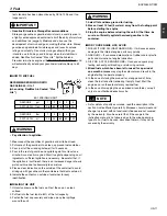
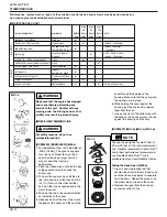
ADJUSTING THROTTLE CABLE

• The normal play is 1 or 2mm when

measured at the carburetor side end.
Readjust with the cable adjuster as
required. (OP5)

(1) cable adjuster

ADJUSTING IDLING SPEED (OP6)

1. When the engine tends stop frequently

at idling mode, turn the adjusting screw
clockwise.

2. When the cutting head keeps rotating

after releasing the trigger, turn the
adjusting screw counter-clockwise.

(1) idle adjusting screw

• Warm up the engine before adjusting

the idling speed. 

NOTE

IMPORTANT

NOTE

(1)

OP6

.04 in

(1~2mm)

(1)

OP5

Summary of Contents for BCZ2450S

Page 1: ...st from this product contains chemicals known to the State of California to cause cancer birth defects or other reproductive harm WARNING Before using our products please read this manual carefully to...

Page 2: ...the machine 4 5 For safe operation 5 6 Set up 9 7 Fuel 10 8 Operation 12 9 Maintenance 14 10 Storage 16 11 Disposal 16 12 Optional blade usage 17 13 Troubleshooting guide 20 Contents 1 Read this brus...

Page 3: ...BCZ3050S BCZ3050T 12 1 lbs 5 49 kg 12 94 lbs 5 87 kg Including line head BCZ3050SW 12 76 lbs 5 79 kg 13 60 lbs 6 17 kg Including line head Engine Type Air cooled 2 stroke gasoline Model GZ30N Displace...

Page 4: ...from which you purchased the product to order new labels and affix them in the required location s Never modify your brushcutter Do not attach any metal blade to BCZ3050T We won t warrant the machine...

Page 5: ...fe operation b Approved ear protection to reduce the risk of hearing loss c Approved ANSI Z87 1 eye protection and foot protection to reduce the risk of injury associated with thrown objects d Face fi...

Page 6: ...the ground in a flat clear area and hold it firmly in IMPORTANT WARNING 5 For safe operation place so as to ensure that neither the cutting part nor the throttle come into contact with any obstacle wh...

Page 7: ...or late at night when people might be disturbed Comply with times listed in local ordinances IMPORTANT 2 To reduce sound levels limit the number of pieces of equipment used at any one time 3 Operate...

Page 8: ...nual must be performed please contact a representative from the store nearest RedMax authorized servicing dealer for assistance 6 Do not use any accessory or attachment other than those bearing the Re...

Page 9: ...oose the guard suitable for a line head If the right guard is not used it may lead to a serious accident SE3 1 Guard for Line Head Red T3245 24110 2 Guard for Blade Black T3246 24110 IMPORTANT IMPORTA...

Page 10: ...l engine components damage Poor quality gasolines or oils may damage sealing rings fuel WARNING NOTE WARNING lines or fuel tank of the engine Failures caused by operating engines on gasoline with octa...

Page 11: ...HE UNIT 1 Untwist and remove the fuel cap Rest the cap on a clean surface 2 Put fuel into the fuel tank to 80 of the full capacity 3 Fasten the fuel cap securely and wipe up any fuel spillage around t...

Page 12: ...hoke lever downward to open the choke And restart engine OP2 7 Allow the engine to warm up for several minutes before starting operation 1 When restarting the engine immediately after stopping it leav...

Page 13: ...being cut Heavy growth will require slower action than will light growth 4 Never swing the unit so hard as you are in danger of losing your balance or control of the unit 5 Try to control the cutting...

Page 14: ...iameter of 095in 2 4mm The spool is capable for a line up to 20feet 6m on the 4 head Avoid using a larger line as it may cut down the trimming performance 2 Pinch the slotted area on the both sides of...

Page 15: ...wist and load installation MA1 c 1 Align notch on bump knob with either insert arrow 2 Insert the two ends of a 20 feet piece of trimmer line into each eyelet Pushing line into the channel of the spoo...

Page 16: ...ee if any oil or grease has worked its way in between the clutch lining and drum and if it has wipe it away using oil free lead free gasoline IMPORTANT MUFFLER Inspect periodically the muffler for loo...

Page 17: ...ing the marked side face the shaft side put the holder and the cover on and fasten the blade with the nut OPT4 1 Cover 3540 13283 2 Holder B 6019 13250 STANDARD 3 Nut T3002 13260 STANDARD BALANCE UNIT...

Page 18: ...incorrectly may cause serious accident to the operator WARNING WARNING WARNING OPT7 OPT6 OPT8 OPT9 Make sure that the blade is not bent warped cracked broken or damaged If you find any error to the bl...

Page 19: ...rreach Keep firm footing and balance 12 Optional blade usage for BCZ3050S SW only MAINTENANCE BLADE Check the blade and the fasteners for looseness cracking or bending Check the cutting edges and refo...

Page 20: ...mm spark plug disconnected retighten Case 2 Engine starts but does not keep running Hard re starting CHECK PROBABLE CAUSES ACTION fuel tank incorrect fuel or staled fuel drain it and with correct fuel...

Page 21: ...ughout the emissions warranty period of two years RedMax must maintain a supply of warranted parts sufficient to meet the expected demand for such parts WARRANTY PERIOD Any warranted part that is sche...

Page 22: ...verage Repair parts and accessories replaced under this warranty are warranted only for the BALANCE of the original unit or accessory warranty period All parts or products replaced under warranty beco...

Page 23: ...d including but not limited to spark plugs filters lubricants starter cords sprockets and debris bags Overheating or carbon scoring failures due to restricted clogged exhaust port blocked spark arrest...

Reviews: