background image

Effective from 29-Jul-21     


       Page | 1 


Tools suggested:  

Step ladder, Saw-stools, Hammer, Rubber Mallet, Secateurs, Scissors, Hacksaw, Square, Tape measure, 

Cordless or Electric drill, Level, String-line, Marker pen, Safety gear (as needed).


Select a site: 


Choose a level site that offers some protection for the Tunnelhouse from strong wind.  Face the door away from the pre-dominant 

wind. We suggest you take your time and allow yourself a weekend to erect the frame and then fit the covering on a warm calm day.  
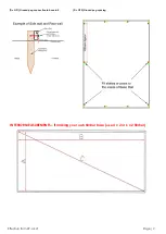
For standard sites, place a 50x50mm x 450-600mm length ground peg at approximately 1m apart around the inside base rail of the 
building. You can then screw the base rail to these pegs.  See below 

Foundation and base rail(s)


I

f you wish to build an additional base frame: 

The tunnelhouse is already supplied with alloy base rails, however if your ground is undulating you may wish to build an additional 

base from 4 x 2 or 6 x 2 timber or some other material. The dimensions for the base are shown on page 2. 
The dimensions shown are the inside measurements enabling the interior base rail of the tunnelhouse to match the inner edges of 

your frame base. Check the level using a builder’s spirit level. Screw or use a bracket to secure the alloy base to your timber base. 

Redpath Pacific Ltd 

PO Box 9058 

16 Bounty Place 

Palmerston North 4414 

Free Ph 0508-733-728 


Summary of Contents for Tunnelhouse

Page 1: ... 1m apart around the inside base rail of the building You can then screw the base rail to these pegs See below Foundation and base rail s If you wish to build an additional base frame The tunnelhouse is already supplied with alloy base rails however if your ground is undulating you may wish to build an additional base from 4 x 2 or 6 x 2 timber or some other material The dimensions for the base ar...

Page 2: ...Effective from 29 Jul 21 Page 2 Pic GP1 Ground peg connection to base rail Pic GP2 Ground peg spacing INTERIOR MEASUREMENTS if making your own timber base use 4 x 2 or 6 x 2 timber ...

Page 3: ...Join the various length of side base rail sections so that they are both of equal length Use two 16mm self drilling screws on the inside face to connect each joint sleeve The groove in the side base rail will face to the outside The groove in the base rail at the door end base rail faces to the inside This is so that the sliding door has clearance from the end wall cladding when the door slides op...

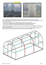
Page 4: ...m into place at this stage see Pic Page 5 IMPORTANT If there is a roof vent those hoops that will have the roof vent located between them will have a gap in the Polyguard protection soft tape at their apex And they should also be positioned so that their smooth flat side faces face toward each other NOTE 1 We suggest not securing the internal hoops with the two screw s at their base saddles until ...

Page 5: ...e the joints sleeve and place screws to the inside face The five purlins are positioned as shown below with the Polyguard soft white felt tape facing to the outside If you have a 15m or longer tunnel fit the collar tie high wind braces as shown in the drawing below NOTE If an optional sidewall or end wall shelf unit is to be fitted the lowest purlin should be placed above the shelf bracket height ...

Page 6: ...ide face of the end hoop using one screw The top end of the brace must stop short of the end hoop otherwise it will damage the end wall covering TIPS TRICKS It can be helpful when you come to fitting the roof side cover to release one end of the sidewall bracing temporarily Then re attach after the roof side cover has been fitted This can assist in adding tension to the covering Note End Side wall...

Page 7: ...on from the tail of the film behind 3 Seat the insert and pull it back into the groove 4 Locate and seat the small 1cm x 1cm Lockstrip clip Pic L1 Use the 200mm green inserts in the front Pic L2 Shows the positioning of the covering red Insert green face of the curved part at each end hoop only and Lockstrip clip on the end hoops Note the direction of the parts Type 2 Duralock The Duralock groove ...

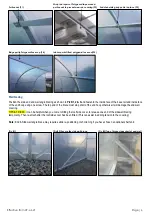
Page 8: ... faces facing toward each other and also have a 200mm gap in the Polyguard tape at the apex Before fitting the roof cover remove the cap vent part plus the aluminium pivot arms and handle leaving the two vent rails and upstand in place See Pics on page 10 NOTE If your Tunnelhouse has a roof vent take care not to catch the cover on the vent rail Unfold the cover and lay it out over the Tunnelhouse ...

Page 9: ...ave a roof vent The two hoops that will have the roof vent fitted in between should have their flat side faces facing toward each other When you have decided which section to place the roof vent in you will need to cut and remove the ridge purlin in that section 1 Before fitting the roof and side covering Lift the roof vent complete into place at the centre apex of the Tunnelhouse The ends of the ...

Page 10: ... the tunnel has had its covers fitted slide the three polycarbonate sheets into place Remove the backing tape from the 570mm aluminium strong back angles and adhere one across the center of each blade to stiffen them Fit the strongback alloy angle across center of each louvre blade to stiffen the polycarbonate double sided tape is included Louvre mechanism is already fitted 150mm Lockstrip insert ...

Page 11: ...through the mount plate of the door track at one end to secure then repeat this at the opposite end see pic page 12 5 Screw three more screws evenly spaced through to the door lintel to fully support the track Place one longer screw into the end hoop to support that end of the door track Check the door sliding action 6 Place a screw through each end of the door track where the door rollers slide t...

Page 12: ...up and over the tunnel shape Redpath includes ropes with this option which pull over and secure the throw over cover in place Throw over Shadecloth for summertime cooling Drawing below shows approximate retaining rope positions and saddles to be screwed to the base rail or base timber Use one rope beside each hoop and place the rope approximatley 200 300mm in from each end If a roof vent is fitted...

Page 13: ...han 3 metres the aluminium shelf slats may have joins and sleeves You will need to join the parts with the sleeves and screws supplied to make the correct length shelf slats INSTALLATION There is one shelf bracket per arch hoop and end studs if a rear wall shelf 1 Position a shelf bracket at each end using three screws into the side face of the uprights Set them at the same height with their top f...

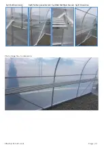
Page 14: ...Effective from 29 Jul 21 Page 14 Fig 1 Fold faces inwards Fig 2 Position rear and front slat Fig 3 Slats finish 30mm from end Fig 4 General view Photo image file for reference ...

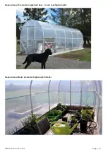
Page 15: ...all shelf example Image gallery below is for reference from archives Note your model may differ in length and options shown Also see on line images at www redpath co nz Base pad prepared ready for construction Dual door option fitted one end ...

Page 16: ...Effective from 29 Jul 21 Page 16 General view 7 5m model single front door 1 x roof vent high wind kit General view interior 6m model high wind kit interior ...

Page 17: ...Effective from 29 Jul 21 Page 17 General view 3m model with high wind kit fitted internal raised gardens included General views Louvre Roof vent ...

Page 18: ...Effective from 29 Jul 21 Page 18 Roof vent internal view Internal end wall view Sidewall shelf option Door systems ...

Page 19: ...or chemical degradation of the covers or alloy Patch any holes or tears in the cover as they happen with Redpath s All weather repair tape or Patchbond tape Check annually that foundations are secure all bracket screws are tight replace any missing or broken screws check that door rollers and vent mechanisms are operating smoothly Replacement tunnelhouse parts are held in stock by Redpath Replacem...

Reviews: