Redpine Signals, Inc.
Page 57
R
R
S
S
-
-
W
W
C
C
-
-
3
3
0
0
1
1
E
E
v
v
a
a
l
l
u
u
a
a
t
t
i
i
o
o
n
n
B
B
o
o
a
a
r
r
d
d
U
U
s
s
e
e
r
r
G
G
u
u
i
i
d
d
e
e
V
V
e
e
r
r
s
s
i
i
o
o
n
n
2
2
.
.
5
5
1
1
10
Using the Module in SPI Mode
To evaluate the module in SPI mode, the following steps should be
followed:
1.
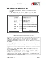
SPI interface of the EVB should be interfaced with the Host MCU.
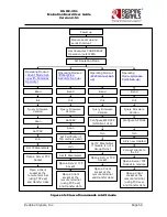
Figure 14: Interface between Module and Host
Signal Integrity Guidelines for SPI interface: Glitches in the SPI clock may take the
SPI interface out of synchronization. The quality and integrity of the clock line
should be maintained. The following steps are recommended. This is not an
exhaustive list of guidelines and depending on individual cases additional steps may
be needed.
1. Avoid using long cables to connect the Host platform with the EVB‟s SPI
interface. If a cable is used, minimize its length to as small as possible, preferably
to within two inches.
2. Increase the number of ground connections between the Wi-Fi PCB and the MCU
PCB
3. Add a series resistor into the clock line. Choice of value is mentioned in the
Module Integration Guide.
4. If the SPI clock line is mapped to a programmable I/O on the MCU, configure
that I/O to an output with as high a drive as is available.
5. Ensure that the EVB‟s reset input is mapped to a MCU controllable line, so that
the system can recover through a hard reset.
Host MCU
SPI MOSI (SPI Header)
SPI MISO (SPI Header)
SPI CLK (SPI Header
SPI CS (SPI Header)
INTERRUPT (SPI Header Pins)
SPI_READY (General Purpose Header)
RS-WC-301
SPI MOSI
SPI MISO
SPI CLK
SPI CS
INTERRUPT
GPIO
RESET_N (General Purpose Header)
RESET_N
GPIO
WAKEUP

