Redpine Signals, Inc.
Page 7
R
R
S
S
-
-
W
W
C
C
-
-
3
3
0
0
1
1
E
E
v
v
a
a
l
l
u
u
a
a
t
t
i
i
o
o
n
n
B
B
o
o
a
a
r
r
d
d
U
U
s
s
e
e
r
r
G
G
u
u
i
i
d
d
e
e
V
V
e
e
r
r
s
s
i
i
o
o
n
n
2
2
.
.
5
5
1
1
2
Components on the EVB
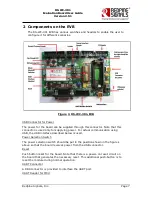
The RS-WC-301 EVB has various switches and headers to enable the user to
configure it for different scenarios.
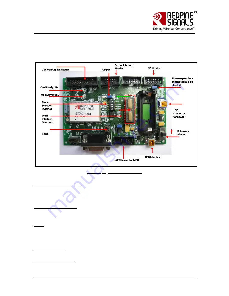
Figure 1: RS-WC-301-EVB
USB Connector for Power
The power for the board can be supplied through this connector. Note that this
connector is used only for supplying power. For actual communication using
USB, the USB interface described below is used.
Power Selection Switch
The power selection switch should be put in the position shown in the figures
above so that the board receives power from the USB connector.
Reset
Push button reset for the board. Note that there is a power-on reset circuit on
the board that generates the necessary reset. This additional push-button is to
reset the module during normal operation.
UART Connector
A DB9 connector is provided to interface the UART port.
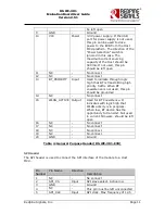
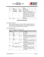
UART Header for MCU


