background image

17

DRY WALL SANDER

OPERATOR STANCE

•  The operator should adopt a comfortable 

stance with their feet apart and  
firmly balanced.

•  Both feet should be on the ground or floor. 

It is not acceptable to have one foot on 
the floor and the other on a stand or ladder 
rung etc, as this precludes the operator 
from achieving a proper balanced stance.

Caution: 

If ‘reach’ or access considerations 

necessitate the use by the operator of a stand-
on platform, such a platform must be suitable, 
in good condition with all the safety features 
serviceable and stable in use e.g. a folding 
inside scaffold or ‘hop-on’ work platform.

WARNING:

 The operator must  

NEVER overstretch.   

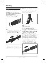
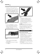
THE ARTICULATED SANDING HEAD

The Sanding Head is attached to the main 
body of the machine by a type of Universal 
Joint. This allows the Sanding Head to 
swivel in multiple directions.

When in use the abrasive disc can effectively 
‘float’ over the work surface. This action 
enables the operator to sweep the work 
surface from top to bottom or from side to 
side with minimal changes to their stance and 
foot position. This affords greater security and 
better balance for the operator.
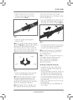
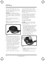
SANDING   

Operational Advice   

•  Configure the machine to the  

‘Reach Mode’ required


•  Connect the required Sanding Head to 

the machine

.

Note: 

The oscillating triangular head is 

particularly useful for gaining access to room 
corners or wall to ceiling boundaries. 


•  Connect a suitable dust extraction and 

collection machine to the Drywall Sander.

•  Turn on the extraction unit.

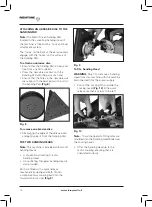
•  Adopt a comfortable stance holding the 

Sander by the two most convenient and 
comfortable hand grips.

•  Turn on the Sander, and if required the 

LED Light.

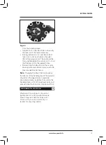
•  Position the Sanding Head lightly against 

the work surface, and apply just enough 
pressure to align the Sanding Head with 
the work surface.

•  Gently apply more pressure to engage 

the abrasive disc onto the work surface.

•  Move the Sander across the work surface 

in long overlapping sweeps. Apply only 
enough pressure to keep the abrasive 
disc flat against the work surface. 
Excessive pressure should be avoided as 
it can cause swirl marks and unevenness 
in the work surface.

•  Keep the Sander in constant motion 

whilst the abrasive disc is in contact 
with the work surface. Use a steady, 
sweeping motion, allowing the rotating 
abrasive disc to ‘float’ over the work 
surface. Moving the Sander erratically 
or concentrating for too long on one 
area can also cause swirl marks or 
unevenness in the work surface.

WARNING:

 Do not allow the rotating 

abrasive disc to contact sharp objects 
such as protruding nails, screws etc or 
architectural wall fittings such as electrical 
boxes or switch plates etc. Damage to the 
Sander or the wall fittings could result.

MAINTENANCE

GB

WARNING:

 Any maintenance must be 

carried out with the machine switched off 
and disconnected from the mains/battery 
power supply.

Check that all safety features and guards  
are operating correctly on a regular basis. 
Only use this machine if all guards/safety 
features are fully operational.

All motor bearings in this machine are lubricated 
for life. No further lubrication is required.

www.leroymerlin.fr

Summary of Contents for 72274475

Page 1: ...Instruction Manual Read instructions before operating this tool www leroymerlin fr PONCEUSE A BRAS TELESCOPIQUE POUR PLAQUE DE PLATRE Manuel d Instruction Merci de lire ces instructions avant d utilis...

Page 2: ...pA KpCpeak and KwA KpA 3 dB KwA 3 dB P The result ah is the basis of declared value If values have been obtained for different hand positions the greatest value shall be the basis for the declaration...

Page 3: ...y 4 General Safety Rules 4 Safety Precautions for Dry Wall Sanders 7 Labels and Symbols 10 Machine Overview 11 Assembly 12 Operational Guidance Advice 16 Maintenance 17 Environmental Protection 19 EC...

Page 4: ...or verbal for consummables In no event shall Redstone be liable for loss or damage resulting directly or indirectly from the use of our merchandise or from any other cause Redstone is not liable for...

Page 5: ...may result in serious personal injury b Use personal protective equipment Always wear eye protection Protective equipment such as dust masks non skid safety shoes hard hat or hearing protection used f...

Page 6: ...result in the ingestion of lead Exposure to even low levels of lead can cause irreversible brain and nervous system damage The young and unborn children are particularly vulnerable You are advised to...

Page 7: ...d route does not pose a trip hazard 6 Always check for damaged parts Before further use of the tool a guard or other part that is damaged should be carefully checked to determine if it will operate pr...

Page 8: ...can be attached to this power tool is not a guarantee of safe operation d The rated speed of the accessory must be at least equal to the specified maximum speed of the power tool Accessories running...

Page 9: ...te the power tool near flammable materials Sparks could ignite these materials p Do not use accessories that require liquid coolants The use of water or other coolants or lubricants may increase the r...

Page 10: ...with a correct abrasive sanding disc this machine can be used to sand Drywall walls and ceilings WARNING This machine is not suitable for sanding materials that may contain asbestos or lead based pro...

Page 11: ...ing Head 3 Hand Grip Areas 4 Auxiliary D Handle 5 LED Light 6 Motor 7 Oscillating Triangular Sanding Head 8 Motor ON OFF switch 9 Motor Speed Control 10 Hose End Connectors x3 11 Dust Extraction Hose...

Page 12: ...ble Hose is protected from being crushed or kinked by the stand Fig 3 LONG REACH MODE Loosen the sleeve nut Fig 1 Remove the Flexible Dust Extraction Hose if fitted Slide the Extension Tube into the m...

Page 13: ...for both right handed and left handed users Insert the Flexible Extraction Hose fully into the end of the Extension Tube and tighten the sleeve nut to secure it in place Fig 7 The free end of the Dus...

Page 14: ...sc and gently peel it from the Sanding Pad THE TWO SANDING HEADS Note This machine is provided with two 2 Sanding Heads A conventional rotating Circular Sanding Head An oscillating Triangular Sanding...

Page 15: ...f the Triangular Sanding Head on its quick release mechanism coupling can be altered Push down on the Locking Button Fig 13 and turn the button to the unlocked position Turn the Triangular Sanding Hea...

Page 16: ...perator should adjust this control to give the most effective dust extraction from the Sanding Head WARNING Even with an effective dust extraction collecting machine attached to this machine the opera...

Page 17: ...ywall Sander Turn on the extraction unit Adopt a comfortable stance holding the Sander by the two most convenient and comfortable hand grips Turn on the Sander and if required the LED Light Position t...

Page 18: ...rom an attached extraction machines sucks the dust away Over time depending upon the frequency of use and the type of material sanded the bristles on the Brush Skirt will become degraded and worn The...

Page 19: ...ors drive spindle and secure in place with the Hex Headed Socket Screw Note Changing the Brush Skirt will expose the interior of the Sanding Head The operator should take the opportunity to examine cl...

Page 20: ...any kind of modifications to question conformity established in the table below D CLARATION DE CONFORMIT FR Report Reference Number Product Reference Product number mentioned in reports Testing Labora...

Page 21: ...www leroymerlin fr 21 PONCEUSE A BRAS TELESCOPIQUE POUR PLAQUE DE PLATRE...

Page 22: ...des incertitudes K KpA KpCpeak and KwA KpA 3 dB KwA 3 dB P Le resultat ah est la base de la valeur d clar e Si la valeur a t obtenue en fonction de positions manuels diff rentes la plus grande valeur...

Page 23: ...de 36 mois 24 R gles g n rales de s curit 24 Consignes de s curit pour la 25 ponceuse a bras telescopique tiquettes et symboles 31 Aper u de la machine 33 Description de la Fonction Operation 34 Cons...

Page 24: ...sation au del des capacit s et sp cifications recommand es Les composants lectriques sont assujettis aux garanties respectives de leur fabricant Redstone se r serve le droit de le r parer ou de le rem...

Page 25: ...ple des tuyaux radiateurs cuisini res r frig rateurs Il y a un risque accru d lectrocution si votre corps est mis la terre c Ne pas exposer les outils lectriques la pluie ou dans des conditions d humi...

Page 26: ...util lectrique avant de faire des r glages de changer les accessoires ou de ranger les outils lectriques Ces mesures de s curit pr ventives r duisent le risque de d marrage de l outil en marche accide...

Page 27: ...blanches syndrome de Raynaud Cette condition peut r duire la sensibilit de la main la temp rature ainsi que produire un engourdissement g n ral Les utilisateurs prolong s ou r guliers de ponceuses dev...

Page 28: ...de parties mobiles Remplacer imm diatement les c bles endommag s Des c bles endommag s augmentent le risque de choc lectrique 8 Veillez ce que toute rallonge que vous utilisez soit en bon tat et si u...

Page 29: ...r ou casser e Le diam tre ext rieur et l paisseur de votre accessoire doivent se situer dans le cadre des caract ristiques de capacit de votre outil lectrique Les accessoires qui sont trop grands ou t...

Page 30: ...ionner I outil lectrique en le portant sur le c t Essayer d utiliser le bord ou l extr mit de l accessoire de rotation augmente le risque d accrochage accidentelle des v tements des op rateurs et la p...

Page 31: ...ser des disques de pon age surdimensionn s dans cette machine Utilisez uniquement la taille des disques abrasifs sp cifi s dans ce manuel d instructions Suivez les recommandations du fabricant lors du...

Page 32: ...Ne pas jeter l emballage gardez le s r tout au long de la p riode de garantie Eliminer l emballage d une mani re cologiquement responsable Recycler si possible Ne permettez pas aux enfants de jouer a...

Page 33: ...E DE PLATRE 1 Tube d extension 2 T te de pon age pivotante 3 Zones de poign e 4 Poign e Auxiliaire D 5 Lampe LED 6 Moteur 7 T te de pon age triangulaire oscillante 8 Interrupteur MARCHE ARR T 9 Comman...

Page 34: ...contre un mur ou un objet similaire Le tuyau flexible est prot g de tout crasement ou d formation caus s par le support Fig 3 MODE LONGUE PORT E Desserrez l crou douille Fig 1 Retirez le tuyau d aspir...

Page 35: ...plus pratique pour la majorit des op rateurs Remarque La conception de la poign e D est telle qu il est possible d obtenir un positionnement ergonomique de la poign e sur l attache Cela garantit une u...

Page 36: ...les crochets sur la surface du patin de pon age Attacher un disque abrasif Assurez vous que le patin de pon age est propre et exempt de toute poussi re ou d bris Pressez le nouveau disque abrasif sur...

Page 37: ...lle s enclenche dans l accouplement moteur Remarque Le fait de bouger l g rement le patin de pon age la main peut aider fixer et enclencher la broche et le mandrin d entra nement Apr s avoir fix la t...

Page 38: ...d acc s des parties de murs difficiles LES COMMANDES DE LA MACHINE L interrupteur glissi re MARCHE ARR T Fig 14 est verrouillable Glissez le vers l avant pour d marrer le moteur Poussez la partie cen...

Page 39: ...a machine Une poign e auxiliaire D est fournie avec la machine elle est particuli rement utile quand la machine est configur e en mode longue port e Placez vos mains le long de la machine de mani re o...

Page 40: ...pression excessive doit tre vit e car elle peut provoquer des rayures et des in galit s sur la surface de travail Assurez un mouvement permanent de la ponceuse lorsque le disque abrasif est en contac...

Page 41: ...r quence d utilisation et du type de mat riaux ponc s les poils de la couronne brosse se d gradent et s usent Les poils de la couronne brosse doivent tre complets sans trous ou portions manquantes Une...

Page 42: ...patin de pon age sur l axe motoris et fixez le avec la vis t te hexagonale Remarque Le changement de la couronne brosse expose l int rieur de la t te de pon age L op rateur doit en profiter pour exam...

Page 43: ...3 2 2014 EN61000 3 3 2013 Le produit n a pas subi de modifications de nature remettre en question la conformit tablie dans le tableau ci dessous D CLARATION DE CONFORMIT FR N Ref du rapport R f rence...

Page 44: ......

Reviews: