background image

14

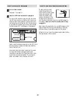
HOW TO USE THE MANUAL MODE

Note: If there is a sheet of clear plastic on the face of
the console, remove the plastic.

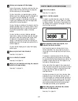
Press any button on the console or begin
pedaling to turn on the console.

When you turn on the console, the display will
light. A tone will then sound and the console will
be ready for use.  

Select the manual mode.

When you turn on the console, the manual mode
will be selected. If you have selected a program,
reselect the manual mode by pressing any of the
Programs buttons repeatedly until zeros appear in
the display.

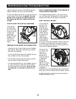
Begin pedaling and change the resistance of
the pedals and the incline of the ramp as
desired.

As you pedal, change the resistance of the ped-
als by pressing the OneTouch Resistance but-
tons. There are fifteen resistance levels. Note:
After you press the buttons, it will take a moment
for the pedals to reach the selected resistance
level. 

To vary the motion of the pedals, you can change
the incline of the ramp. To change the incline,
press the OneTouch Ramp buttons. There are
five incline levels. Note: After you press the but-
tons, it will take a moment for the ramp to reach
the selected incline level. 

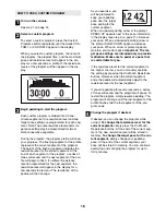
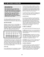
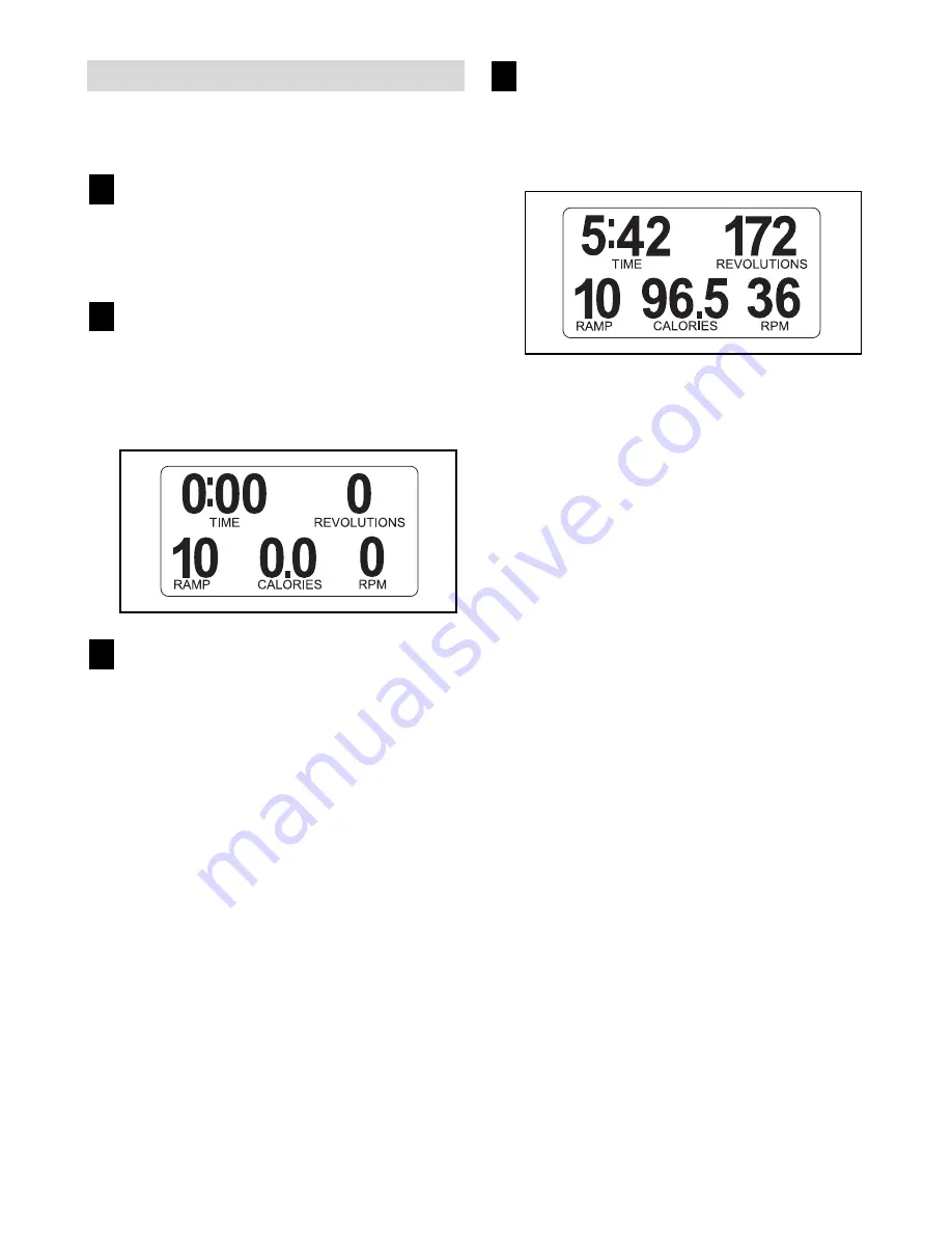
Follow your progress with the display.

While you pedal, the upper left corner of the dis-
play will show the elapsed time. Note: During a
program, except for heart rate program 1, the dis-
play will show the time remaining in the program.

The upper right corner of the display will show the
distance you have pedaled, in total revolutions.
The display will also show your heart rate when
you use the handgrip pulse sensor (see step 5 on
page 15). 

The lower left corner of the display will show the
ramp incline level.

The lower center of the display will show the
approximate number of calories you have burned.

The lower right corner of the display will show
your pedaling pace, in revolutions per minute.

The center of the display will show the resistance
level of the pedals for a few seconds each time the
resistance level changes.

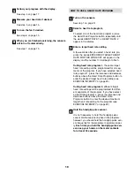
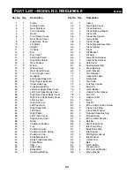
You can also view selected information at a larger
size. Press the Display button repeatedly to view
the elapsed time and the distance you have ped-
aled, the elapsed time and the approximate num-
ber of calories you have burned, or the elapsed
time. Press the Display button again to view a
workout history of resistance levels and pedaling
pace.

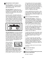
To again view the time, distance, ramp incline,
number of calories burned, and pedaling pace,
press the Display button again. 

To view the total distance pedaled since the ellipti-
cal exerciser was purchased and the trip distance,
press the Odometer button. The information will
appear in the display for a few seconds. To reset
the trip distance, hold down the Odometer button
for a few seconds.

4

3

2

1

Summary of Contents for 100 Zx Elliptical

Page 1: ...website at www reebokhomefitness com new products prizes fitness tips and much more USER S MANUAL QUESTIONS As a manufacturer we are com mitted to providing complete customer satisfaction If you have...

Page 2: ...NG 22 CONDITIONING GUIDELINES 23 PART LIST 24 EXPLODED DRAWING 26 HOW TO ORDER REPLACEMENT PARTS Back Cover LIMITED WARRANTY Back Cover 2 TABLE OF CONTENTS REEBOK and the Vector Logo are registered tr...

Page 3: ...an 325 pounds 8 Wear appropriate exercise clothes while using the elliptical exerciser Always wear athletic shoes for foot protection while exer cising 9 Hold the handgrip pulse sensors or the upper b...

Page 4: ...r and serial number before con tacting us The model number is RBEL9906 0 The serial number can be found on a decal attached to the elliptical exerciser see the front cover of this manual for the locat...

Page 5: ...pages 24 and 25 The number follow ing the parentheses is the quantity needed for assembly Note Some small parts may have been preassem bled If a part is not in the parts bag check to see if it has be...

Page 6: ...25mm Washer 87 onto an M10 x 20mm Button Screw 111 Tighten the Button Screw into one end of the Ramp Axle 72 Apply a small amount of the included grease to the Ramp Axle Orient the Ramp 5 as shown Al...

Page 7: ...dal Arm Latch make sure that the Left Pedal Arm is securely connected to the Crank Bushing Sleeve Connect the Right Pedal Arm 33 to the right Crank Bushing Sleeve not shown in the same way 7 4 Identif...

Page 8: ...e Upright 10 near the Frame 1 connect the Upper Wire Harness 65 to the Lower Wire Harness 64 Carefully insert the Upright 10 into the Frame 1 be careful not to damage the Wire Harnesses 64 65 Attach t...

Page 9: ...Left Link Arm 30 into the left Upper Body Leg 24 while sliding the Left Link Arm onto the axle on the Left Pedal Arm 32 Repeat this step with the Right Link Arm 31 9 32 100 30 Grease Grease 31 24 74 8...

Page 10: ...66 a Link Arm Spacer 74 and an M8 x 15mm Button Screw 106 as shown Attach the Right Link Arm 31 in the same way 11 Plug the power cord not shown into the power socket not shown at the rear of the elli...

Page 11: ...o determine if the outlet box cover is grounded before using an adapter HOW TO FOLD AND UNFOLD THE ELLIPTICAL EXERCISER When the elliptical exerciser is not in use the frame can be folded out of the w...

Page 12: ...tep onto the pedal that is in the lowest posi tion Next step onto the other pedal Push the pedals until they begin to move with a continuous motion Note The crank arms can turn in either direction It...

Page 13: ...so features the new iFIT Interactive Workout System The iFIT Interactive Workout System enables the console to accept iFIT Cards containing workout programs designed to help you achieve specif ic fitn...

Page 14: ...time Note During a program except for heart rate program 1 the dis play will show the time remaining in the program The upper right corner of the display will show the distance you have pedaled in to...

Page 15: ...to squeeze the metal contacts tightly For optimal performance clean the metal contacts using a soft cloth never use alcohol abrasives or chemicals to clean the contacts Turn on the fan if desired To...

Page 16: ...he program a series of tones will sound and the next segment of the profile will begin to flash If a different resistance level is pro grammed for the next segment the resistance level will appear in...

Page 17: ...5 HOW TO CREATE A CUSTOM PROGRAM Turn on the console See step 1 on page 14 Select a custom program To select a custom program press the Custom Programs button once or twice When you select a custom pr...

Page 18: ...mpted to keep your pedaling pace near the target pace setting for the current segment When an upward pointing arrow or the prompt SPEED UP appears next to the pace information in the display see step...

Page 19: ...et heart rate setting will be programmed for all seg ments of the program If you have selected heart rate program 1 press the increase and decrease buttons above the Heart Rate Programs button to ente...

Page 20: ...t is too high or too low you can manually override the setting by pressing the OneTouch Resistance buttons However when the console compares your heart rate to the target heart rate setting the resist...

Page 21: ...oice of a personal trainer will begin guiding you through your workout iFIT programs work in the same way as preset programs To use the pro gram see steps 3 to 6 on pages 16 and 17 HOW TO USE THE STER...

Page 22: ...h a soft cloth never use alco hol abrasives or chemicals to clean the con tacts HOW TO ELIMINATE FLEXING IN THE CENTER OF THE ELLIPTICAL EXERCISER If the elliptical exerciser flexes in the center duri...

Page 23: ...ascular sys tem your exercise must be aerobic Aerobic exer cise is activity that requires large amounts of oxygen for prolonged periods of time This increases the demand on the heart to pump blood to...

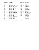
Page 24: ...Block 47 1 Idler 48 1 Idler Pulley 49 1 Eddy Motor 50 1 Reed Switch Wire 51 1 Clamp 52 2 Large Axle Cover 53 2 Crank Bushing 54 2 Crank Bushing Sleeve 55 2 Crank Arm 56 1 Crank Arm Spacer 57 1 Large...

Page 25: ...tton Screw 112 8 M8 x 25mm Shoulder Screw 113 2 M8 x 30mm Button Screw 114 5 1 4 x 19mm Button Screw 115 3 M4 x 12mm Screw 116 54 M4 x 16mm Screw 117 8 M4 x 16mm Cupped Screw 118 4 M6 Nylon Locknut 11...

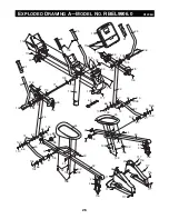
Page 26: ...66 66 67 67 66 67 67 67 67 67 67 119 119 119 119 120 120 71 74 74 74 89 89 116 116 110 103 103 105 104 106 116 116 117 116 116 116 117 116 104 105 106 116 116 115 100 100 106 103 110 103 106 103 100 1...

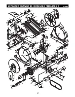
Page 27: ...80 81 82 82 83 83 84 85 84 85 86 86 87 88 88 88 90 91 92 94 73 93 93 118 118 96 99 99 107 101 107 101 116 116 116 116 111 87 116 116 116 111 87 102 114 102 114 114 116 116 113 103 113 103 112 110 110...

Page 28: ...arran ty does not extend to any product or damage to a product caused by or attributable to freight damage abuse misuse improper or abnormal usage or repairs not provided by an ICON authorized service...

Reviews: