background image

21

Most treadmill problems can be solved by follow-
ing the simple steps below. Find the symptom that 
applies, and follow the steps listed. If further assis-
tance is needed, see the front cover of this manual. 

SYMPTOM: The power does not turn on

a.   Make sure that the power cord is plugged into a 

surge suppressor and that the surge suppressor 
is plugged into a properly grounded outlet (see 
page 13). Use only a surge suppressor that meets 
all of the specifications described on page 13. 

IMPORTANT: The treadmill is not compatible 
with GFCI-equipped outlets and may not be 
compatible with AFCI-equipped outlets.

b.   After the power cord has been plugged in, make 

sure that the key is inserted into the console.

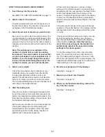
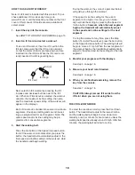
c.   Check the power switch located on the treadmill 

frame near the power cord. If the switch protrudes 
as shown, the switch has tripped. To reset the 
power switch, wait for five minutes and then press 
the switch back in.

SYMPTOM: The power turns off during use

a.   Check the power switch (see the drawing above). 

If the switch has tripped, wait for five minutes and 
then press the switch back in.

b.   Make sure that the power cord is plugged in. If the 

power cord is plugged in, unplug it, wait for five 
minutes, and then plug it back in.

c.   Remove the key from the console, and then        

reinsert it.

d.   If the treadmill still will not run, please see the front 

cover of this manual.

SYMPTOM: The displays of the console do not 
function properly

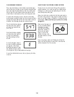
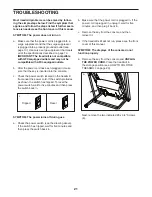
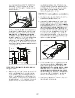
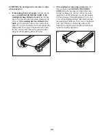
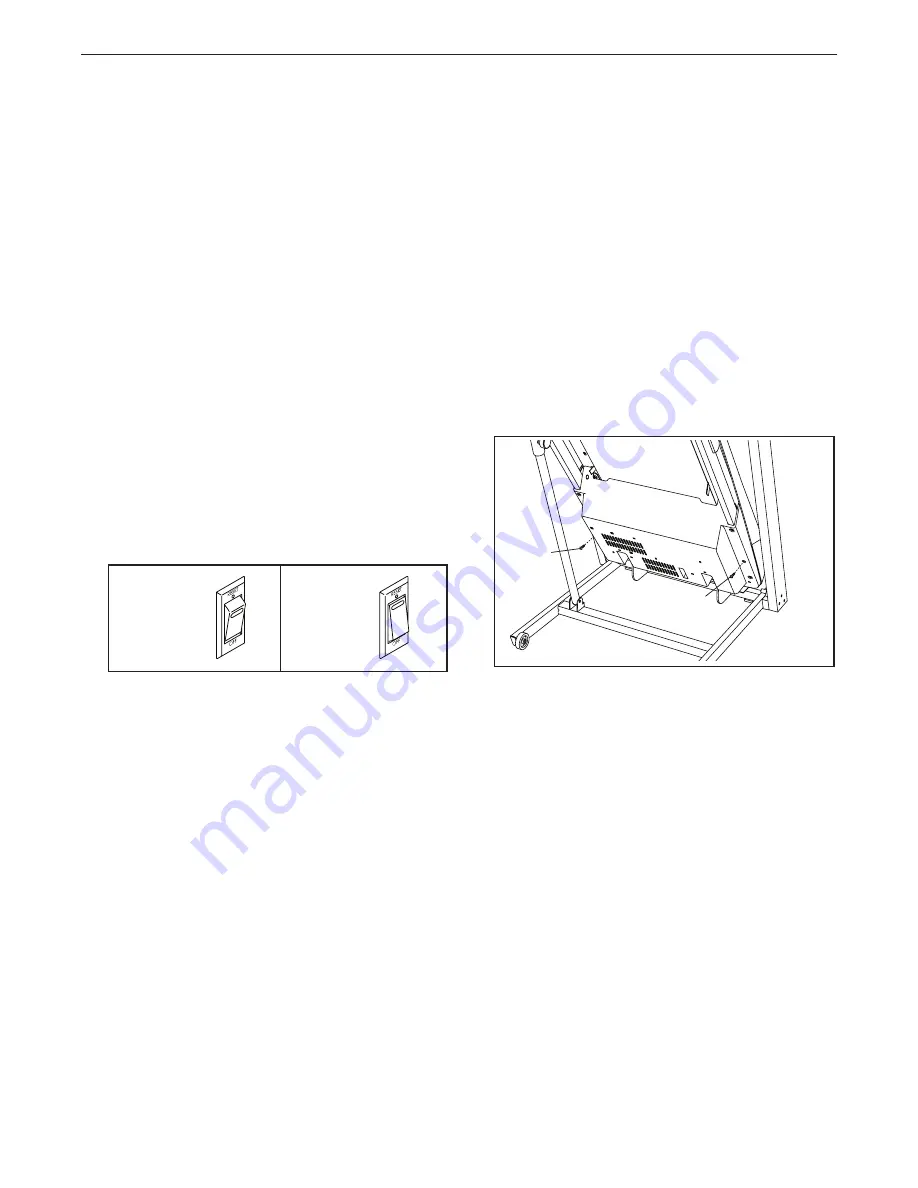
a.    Remove the key from the console and 

UNPLUG 

THE POWER CORD.

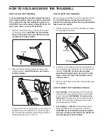
 Place the treadmill in 

the storage position (see HOW TO FOLD THE 
TREADMILL on page 20).


 Next, remove the two indicated #8 x 3/4" Screws 
(6).

TROUBLESHOOTING

Reset

Tripped

c

6

6

a

Summary of Contents for Challenger 150 Treadmill

Page 1: ...nce QUESTIONS If you have questions or if parts are damaged or missing DO NOT CONTACT THE STORE please contact Customer Care IMPORTANT Please register this product see the limited warranty on the back cover of this manual before contacting Customer Care CALL TOLL FREE 1 877 994 4999 Mon Fri 6 a m 6 p m MT Sat 8 a m 4 p m MT ON THE WEB www reebokservice com www reebokfitness com Serial Number Decal...

Page 2: ...RTS Back Cover LIMITED WARRANTY Back Cover This drawing shows the locations of the warn ing decals If a decal is missing or illegible call the telephone number on the front cover of this manual and request a free replacement decal Apply the decal in the location shown Note The decals may not be shown at actual size TABLE OF CONTENTS REEBOK and the Vector Logo are registered trademarks and service ...

Page 3: ... cell phone chargers into the surge suppressor or into an outlet on the same circuit 12 Use only a surge suppressor that meets all of the specifications described on page 13 To purchase a surge suppressor see your local REEBOK dealer call the telephone number on the front cover of this manual or see your local electronics store 13 Failure to use a properly functioning surge suppressor could result...

Page 4: ...n 23 Never insert any object into any opening on the treadmill 24 Inspect and properly tighten all parts of the treadmill regularly 25 DANGER Always unplug the power cord immediately after use before clean ing the treadmill and before performing the maintenance and adjustment procedures described in this manual Never remove the motor hood unless instructed to do so by an authorized service represe...

Page 5: ...see the front cover of this manual To help us assist you note the product model number and serial number before contacting us The model number and the location of the serial number decal are shown on the front cover of this manual Before reading further please familiarize yourself with the parts that are labeled in the drawing below BEFORE YOU BEGIN Handrail Tray Key Clip Power Switch Walking Belt...

Page 6: ...he end of this manual The number following the key number is the quantity used for assembly Note If a part is not in the hardware kit check to see if it is preat tached Extra hardware may be included 8 x 1 2 Ground Screw 1 1 8 x 3 4 Screw 6 12 1 4 x 1 Screw 9 4 5 16 x 1 Bolt 7 8 3 8 x 1 3 4 Screw 12 1 3 8 x 2 Bolt 13 1 3 8 x 3 1 2 Screw 4 6 5 16 Star Washer 8 8 3 8 Star Washer 5 6 3 8 Nut 3 1 ...

Page 7: ...aner To identify small parts see page 6 Assembly requires the following tools the included hex keys one adjustable wrench one Phillips screwdriver scissors needlenose pliers To avoid damaging parts do not use power tools 1 Make sure that the power cord is unplugged Remove the ties securing the Upright Wire 70 to the Base 80 Pull the Upright Wire and the base ground wire A through the indicated hol...

Page 8: ...r end of the Left Upright as you pull the other end of the wire tie through the Left Upright 2 70 75 75 Wire Tie 70 Wire Tie 80 3 Hold the Left Upright 75 against the Base 80 Be careful not to pinch the wires Partially tighten three 3 8 x 3 1 2 Screws 4 with three 3 8 Star Washers 5 into the Left Upright and the Base do not fully tighten the Screws yet Attach the Right Upright not shown in the sam...

Page 9: ... 7 and three 5 16 Star Washers 8 as shown Be careful not to pinch the Upright Wire 70 Start all three Bolts before tightening them Attach the Right Handrail not shown in the same way Note There are no wires on the right side 71 70 33 7 4 7 8 75 5 Identify the Left Handrail Tube 10 which is marked Left Insert the Left Handrail Tube 10 into the top of the Left Handrail 71 Attach the Left Handrail Tu...

Page 10: ...ng them 72 71 7 7 8 8 7 Console Assembly Console Assembly Wire Tie 70 6 70 75 Console Wire 6 With the help of a second person hold the con sole assembly near the Left Upright 75 Connect the Upright Wire 70 to the console wire See the inset drawing The connectors should slide together easily and snap into place If they do not turn one connector and try again IF YOU DO NOT CONNECT THE CON NECTORS PR...

Page 11: ...and then tighten them Do not overtighten the Screws 10 11 6 8 Console Assembly 6 9 Identify the Left Tray 87 and the Right Tray 88 Make sure that the indicated notch is positioned as shown Attach the Trays with eight 8 x 3 4 Screws 6 Start all eight Screws and then tighten them Do not overtighten the Screws 6 88 87 9 Notch 6 ...

Page 12: ...2 3 13 80 Large Barrel 11 11 Raise the Frame 49 to the position shown Have a second person hold the Frame until this step is completed Orient the Storage Latch 51 so that the large barrel and the latch knob are oriented as shown Attach the lower end of the Storage Latch 51 to the Base 80 with a 3 8 x 2 Bolt 13 and a 3 8 Nut 3 Attach the upper end of the Storage Latch 51 to the Frame 49 with a 3 8 ...

Page 13: ...d into a surge suppressor and plug the surge suppressor into an appropriate outlet that is properly installed and grounded in accordance with all local codes and ordinances The outlet must be on a nominal 120 volt circuit capable of carrying 15 or more amps To avoid overloading the circuit do not plug other electrical devices except for low power devices such as cell phone chargers into the surge ...

Page 14: ...admill iFit cards are available separately To purchase iFit cards at any time go to www iFit com or call the telephone number on the front cover of this manual iFit cards are also available at select stores You can even listen to your favorite workout music or audio books with the console s premium stereo sound system while you get in shape To turn on the power see page 15 To use the manual mode s...

Page 15: ... the manual mode will be selected If a weight loss workout has been selected remove the key and then reinsert it 3 Start the walking belt To start the walking belt press the Go button the Speed increase button or one of the Quick Speed buttons numbered 1 through 10 If you press the Go button or the Speed increase button the walking belt will begin to move at 1 mph As you exercise change the speed ...

Page 16: ...is display will show your heart rate when you use the handgrip heart rate monitor This display will also show the speed of the walking belt To reset the displays press the Stop button remove the key and then reinsert the key 6 Measure your heart rate if desired Before using the handgrip heart rate monitor first remove the sheets of plastic from the metal contacts In addi tion make sure that your h...

Page 17: ...e first speed and incline settings of the workout Hold the handrails and begin walking Each workout is divided into one minute segments One speed setting and one incline setting are programmed for each segment Note The same speed setting and or incline setting may be pro grammed for consecutive segments At the end of each segment a series of tones will sound If a different speed or incline setting...

Page 18: ...ill will automatically adjust to the first speed and incline settings of the workout Hold the handrails and begin walking During the workout the voice of a personal trainer will guide you through the workout If the speed or incline setting for the current segment is too high or too low you can manu ally override the setting by pressing the Speed or Incline buttons however when the next segment beg...

Page 19: ...r in the Heart Rate Speed display Press the Speed increase button to change the unit of measurement if desired To exit the information mode remove the key from the console HOW TO USE THE STEREO SOUND SYSTEM To play music or audio books through the console s stereo speakers you must connect your MP3 player CD player or other personal audio player to the con sole through the audio jack Plug one end ...

Page 20: ...d in the storage position Moving the treadmill may require two people 1 Hold the frame and one of the handrails and place one foot against a wheel 2 Pull back on the handrail until the treadmill will roll on the wheels and carefully move it to the desired location CAUTION Do not move the tread mill without tipping it back do not pull on the frame and do not move the treadmill over an uneven surfac...

Page 21: ...h located on the treadmill frame near the power cord If the switch protrudes as shown the switch has tripped To reset the power switch wait for five minutes and then press the switch back in SYMPTOM The power turns off during use a Check the power switch see the drawing above If the switch has tripped wait for five minutes and then press the switch back in b Make sure that the power cord is plugge...

Page 22: ...line increase or decrease button again When the incline is calibrated remove the key from the console SYMPTOM The walking belt slows when walked on a Use only a surge suppressor that meets all of the specifications described on page 13 b If the walking belt is overtightened treadmill per formance may decrease and the walking belt may become damaged Remove the key and UNPLUG THE POWER CORD Using th...

Page 23: ...n plug in the power cord insert the key and run the treadmill for a few minutes Repeat until the walking belt is centered b If the walking belt slips when walked on first remove the key and UNPLUG THE POWER CORD Using the hex key turn both idler roller screws clockwise 1 4 of a turn When the walk ing belt is correctly tightened you should be able to lift each edge of the walking belt 2 to 3 in 5 t...

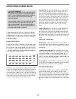
Page 24: ...ic Exercise If your goal is to strengthen your cardiovascular system you must perform aerobic exercise which is activity that requires large amounts of oxygen for prolonged periods of time For aerobic exercise adjust the intensity of your exercise until your heart rate is near the highest number in your training zone WORKOUT GUIDELINES Warming Up Start with 5 to 10 minutes of stretch ing and light...

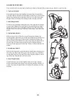
Page 25: ...illes Stretch With one leg in front of the other reach forward and place your hands against a wall Keep your back leg straight and your back foot flat on the floor Bend your front leg lean forward and move your hips toward the wall Hold for 15 counts then relax Repeat 3 times for each leg To cause further stretching of the achilles tendons bend your back leg as well Stretches Calves achilles tendo...

Page 26: ...26 NOTES ...
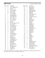
Page 27: ...6 1 Drive Motor Belt 47 1 Drive Motor 48 2 Frame Spacer 49 1 Frame 50 1 Right Foot Rail 51 1 Storage Latch 52 1 Right Rear Foot 53 1 Left Rear Foot 54 1 Right Speaker Back 55 1 Left Speaker Back 56 1 Idler Roller 57 1 Motor Hood 58 2 Incline Frame Spacer 59 1 Incline Frame 60 1 Incline Motor 61 1 Controller Ground Wire 62 1 Controller 63 3 Wire Tie 64 1 Belly Pan Plate 65 1 Power Switch 66 1 Power...

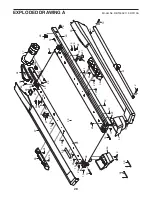
Page 28: ... 42 38 39 50 49 14 34 37 32 27 23 47 29 42 28 29 28 19 19 19 14 53 3 52 25 40 43 44 12 46 48 48 19 45 19 19 19 19 19 13 1 16 16 35 56 95 19 36 24 36 24 29 19 19 29 19 24 24 19 19 EXPLODED DRAWING A Model No RBTL60211 0 R0113A ...

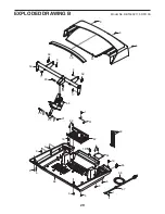
Page 29: ...29 94 1 66 67 65 61 63 62 1 58 59 58 18 20 21 60 22 6 57 6 64 3 3 17 17 20 21 6 18 18 6 6 6 6 6 68 6 6 30 6 6 EXPLODED DRAWING B Model No RBTL60211 0 R0113A ...

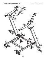
Page 30: ... 15 77 15 78 2 81 3 96 3 2 81 96 79 67 1 96 96 79 79 79 77 77 26 26 4 5 5 4 4 5 10 9 74 7 69 33 7 8 8 9 75 70 7 33 7 8 7 8 69 74 11 77 71 73 76 7 72 73 8 8 6 6 6 6 EXPLODED DRAWING C Model No RBTL60211 0 R0113A ...

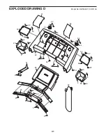
Page 31: ...31 91 6 83 84 86 87 90 6 82 6 6 6 89 1 54 6 92 92 92 92 6 31 55 92 92 6 6 92 6 6 6 94 6 6 6 6 92 92 84 88 94 93 EXPLODED DRAWING D Model No RBTL60211 0 R0113A ...

Page 32: ...o freight damage to the product This warranty will automatically be voided if the product is used as a store display model if the product is purchased or transported outside the USA if all instructions in this manual are not followed if the product is abused or improperly or abnormally used or if the product is used for commercial or rental purposes No other warranty beyond that speci cally set fo...

Reviews: