background image

3

IMPORTANT PRECAUTIONS

    WARNING:

 To reduce the risk of serious injury, read all important precautions and 

instructions in this manual and all warnings on your elliptical before using your elliptical. ICON 
assumes no responsibility for personal injury or property damage sustained by or through the use of 
this product.

1.  Before beginning any exercise program, 

consult your physician. This is especially 
important for persons over age 35 or per-
sons with pre-existing health problems.

2.  Use the elliptical only as described in this 

manual. 

3.  It is the responsibility of the owner to ensure 

that all users of the elliptical are adequately 
informed of all precautions.

4.  The elliptical is intended for home use only. 

Do not use the elliptical in a commercial, 
rental, or institutional setting.

5.  Keep the elliptical indoors, away from mois-

ture and dust. Do not put the elliptical in a 
garage or covered patio, or near water. 

6.  Place the elliptical on a level surface, with at 

least 3 ft. (0.9 m) of clearance in the front and 
rear of the elliptical and 2 ft. (0.6 m) on each 
side. To protect the floor or carpet from dam-
age, place a mat under the elliptical.

7.  Inspect and properly tighten all parts regu-

larly. Replace any worn parts immediately.

8.  Keep children under age 12 and pets away 

from the elliptical at all times.

9.  The elliptical should not be used by persons 

weighing more than 300 lbs. (136 kg).

10. Wear appropriate clothes while exercising; 

do not wear loose clothes that could become 
caught on the elliptical. Always wear athletic 
shoes for foot protection while exercising.

11. Hold the handlebars or the upper body arms 

when mounting, dismounting, or using the 
elliptical.

12. The heart rate monitor is not a medical 

device. Various factors may affect the accu-
racy of heart rate readings. The heart rate 
monitor is intended only as an exercise aid 
in determining heart rate trends in general.

13. The elliptical does not have a freewheel; the 

pedals will continue to move until the fly-
wheel stops. Reduce your pedaling speed in 
a controlled way.

14. Keep your back straight while using the ellip-

tical; do not arch your back.

15. Over exercising may result in serious injury 

or death. If you feel faint or if you experience 
pain while exercising, stop immediately and 
cool down.

Summary of Contents for R 5.10

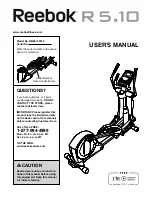
Page 1: ... in the space above for reference QUESTIONS If you have questions or if parts are damaged or missing DO NOT CONTACT THE STORE please contact Customer Care IMPORTANT Please register this product see the limited warranty on the back cover of this manual before contacting Customer Care CALL TOLL FREE 1 877 994 4999 Mon Fri 6 a m 6 p m MT Sat 8 a m 4 p m MT ON THE WEB www reebokservice com Serial Numb...

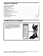
Page 2: ...G 29 ORDERING REPLACEMENT PARTS Back Cover LIMITED WARRANTY Back Cover This drawing shows the location s of the warning decal s If a decal is missing or illegible see the front cover of this manual and request a free replacement decal Apply the decal in the location shown Note The decal s may not be shown at actual size REEBOK and the Vector Logo are registered trademarks and service marks of Reeb...

Page 3: ...tical and 2 ft 0 6 m on each side To protect the floor or carpet from dam age place a mat under the elliptical 7 Inspect and properly tighten all parts regu larly Replace any worn parts immediately 8 Keep children under age 12 and pets away from the elliptical at all times 9 The elliptical should not be used by persons weighing more than 300 lbs 136 kg 10 Wear appropriate clothes while exercising ...

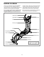
Page 4: ...see the front cover of this manual To help us assist you note the product model number and serial number before contacting us The model number and the location of the serial number decal are shown on the front cover of this manual Before reading further please familiarize yourself with the parts that are labeled in the drawing below Heart Rate Monitor Upper Body Arm Access Cover Wheel Pedal Access...

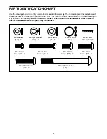
Page 5: ...mm Screw 123 8 PART IDENTIFICATION CHART Use the drawings below to identify the small parts needed for assembly The number in parentheses below each drawing is the key number of the part from the PART LIST near the end of this manual The number following the key number is the quantity needed for assembly Note If a part is not in the hardware kit check to see if it has been preassembled Extra parts...

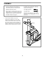
Page 6: ...addition to the included tool s assembly requires the following tools one Phillips screwdriver one rubber mallet Assembly may be easier if you have a set of wrenches To avoid damaging parts do not use power tools ASSEMBLY 1 Orient the Rear Stabilizer 4 as shown Attach the Rear Stabilizer 4 to the Folding Frame 2 with two M10 x 95mm Screws 100 Next hold the handle on the Rear Stabilizer 4 press the...

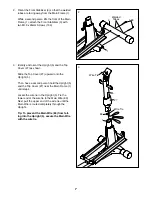
Page 7: ...ver 27 as shown Slide the Top Cover 27 upward onto the Upright 5 Then have a second person hold the Upright 5 and the Top Cover 27 near the Main Frame 1 until step 4 Locate the wire tie in the Upright 5 Tie the lower end of the wire tie to the Main Wire 60 Next pull the upper end of the wire tie until the Main Wire is routed completely through the Upright Tip To prevent the Main Wire 60 from fall ...

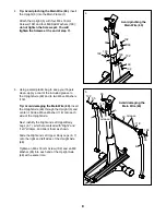
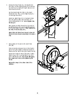
Page 8: ...the Upright Axle 48 and to two Wave Washers 118 Tip Avoid damaging the Main Wire 60 Insert the Upright Axle 48 through the Upright 5 and center it Slide a Wave Washer 118 onto each side of the Upright Axle Next identify the Right and Left Upper Body Legs 6 7 which are marked with Right and Left stickers and orient them as shown Slide the Right and Left Upper Body Legs 6 7 onto the right and left s...

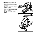
Page 9: ...to the Right Pedal Arm 12 and the Right Pedal 14 Then tighten the two M6 x 12mm Screws 111 Attach the Left Pedal not shown to the Left Pedal Arm not shown assembly in the same way 6 14 12 111 112 112 62 104 7 Apply grease to the axle on the right Crank Arm 39 Orient a Pedal Arm Sleeve 46 so that the flat side is facing the elliptical Slide the Pedal Arm Sleeve onto the axle on the right Crank Arm ...

Page 10: ...oller 32 on the left side of the Ramp 130 See drawing 8b Pull upward on the Latch 50 on the Left Pedal Arm 13 Press the Left Pedal Arm 13 onto the left Pedal Arm Sleeve 46 Make sure that the Left Pedal Arm latches into place Repeat this step on the other side of the elliptical 32 13 130 8b 46 13 50 ...

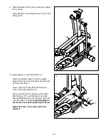
Page 11: ...Using a second hex key tighten another M8 x 35mm Screw 137 a Small Axle Cover 56 and an M8 Washer 95 into the other end of the Link Arm Axle 114 Tip Avoid damaging the Small Axle Cover when tightening the Screw Repeat this step on the other side of the elliptical 10 9 Orient the Ramp Cover 131 around the Upright 5 as shown Press the tabs on the Ramp Cover 131 into the Ramp 130 9 131 130 5 95 43 56...

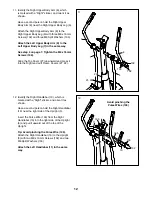
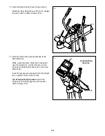
Page 12: ...102 Slide the Top Cover 27 downward and press it into the Right and Left Frame Covers 21 22 12 Identify the Right Handlebar 10 which is marked with a Right sticker and orient it as shown Have a second person hold the Right Handlebar 10 near the right side of the Upright 5 Insert the Pulse Wire 105 from the Right Handlebar 10 into the right side of the Upright 5 and pull it upward out of the top of...

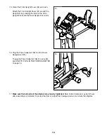
Page 13: ...60 and to the Pulse Wires 105 Insert the excess wire downward into the Upright 5 or upward into the Console 33 Tip Avoid pinching the wires Attach the Console 33 to the Upright 5 with four M4 x 19mm Screws 123 105 5 60 25 123 5 13 Orient the Rear Upright Cover 25 as shown Attach the Rear Upright Cover 25 to the Upright 5 with four M4 x 19mm Screws 123 Avoid pinching the wires 33 123 ...

Page 14: ...ce a mat under the elliptical 24 25 15 Orient the Front Upright Cover 24 as shown Attach the Front Upright Cover 24 around the Upright 5 by pressing the tabs on the Front Upright Cover into the Rear Upright Cover 25 5 15 138 16 Plug the Power Adapter 138 into the Power Receptacle 135 To plug the Power Adapter 138 into an outlet see HOW TO PLUG IN THE POWER ADAPTER on page 16 135 16 ...

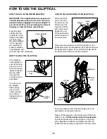
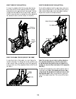
Page 15: ...ng use turn the center leveling foot until the flexing motion is eliminated HOW TO FOLD AND UNFOLD THE ELLIPTICAL When the ellipti cal is not in use the frame can be folded out of the way First lift the latch under each pedal arm and lift the pedal arms off the sleeves on the crank arms Next raise the pedal arms until the magnets on the pedal arms touch the handlebars the magnets will hold the ped...

Page 16: ...he frame HOW TO EXERCISE ON THE ELLIPTICAL To mount the elliptical hold the upper body arms and step onto the pedal that is in the lowest position Next step onto the other pedal Push the pedals until they begin to move with a continuous motion Note The crank arms can turn in either direction It is recommended that you turn the crank arms in the direction shown by the arrow however for variety you ...

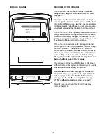
Page 17: ...ctive workout The console also features an iFit training mode that allows you to connect to your wireless network through an iFit Live module The optional iFit Live module allows you to download personalized workouts and to track and analyze workout information on the iFit Live website To purchase an iFit Live module at any time go to www iFit com or call the telephone num ber on the front cover o...

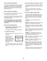
Page 18: ...e the resistance of the pedals by pressing the Resistance increase and decrease buttons Note After you press the buttons it will take a moment for the pedals to reach the selected resis tance level 4 Follow your progress with the display The console offers several display modes The display mode that you select will determine which workout information is shown Press the Display button repeatedly to...

Page 19: ...button on the console to turn on the console See HOW TO ACTIVATE THE CONSOLE on page 18 2 Select a preset workout If you have selected a workout or the iFit Training mode press the Menu button to return to the main menu To select a preset workout first press the increase and decrease buttons next to the Enter button and highlight WORKOUTS Then press the Enter button Next press the increase and dec...

Page 20: ...ing pace IMPORTANT The target rpm is intended only to provide motivation Your actual pedaling pace rpm may be slower than the target rpm Make sure to pedal at a pace that is comfortable for you If the resistance level for the current segment is too high or too low you can manually override the setting by pressing the Resistance buttons IMPORTANT When the current segment of the workout ends the ped...

Page 21: ...y plugged in Next press the play button on your MP3 player or CD player Adjust the volume level using the volume control on your MP3 player or CD player or press the Volume increase and decrease buttons on the console HOW TO USE THE INFORMATION MODE The console features an information mode that allows you to view usage information select a unit of mea surement for the iFit Live workouts and to adj...

Page 22: ... personal trainer will also appear in the display To change the audio setting press the increase and decrease buttons until the bullet appears next to the words TRAINER VOICE Then press the Enter button repeatedly to turn the voice of the personal trainer ON or OFF 7 Check the status of the iFit Live module if desired To check the status of the iFit Live module press the increase and decrease butt...

Page 23: ... equipment does cause harmful interference to radio or television reception which can be determined by turning the equipment off and on try to correct the interference by one or more of the following measures Reorient or relocate the receiving antenna Increase the separation between the equipment and the receiver Connect the equipment into an outlet on a circuit different from that to which the re...

Page 24: ...he console does not display correct feedback the reed switch should be adjusted To adjust the reed switch first unplug the power adapter Using a flat screwdriver release the tabs on the Access Cover 20 and pry the Access Cover upward off the elliptical Next look into the access opening and locate the Reed Switch 69 Rotate the Large Pulley 74 until a Pulley Magnet 75 is aligned with the Reed Switch...

Page 25: ...d then lift the Left Pedal Arm off the left Pedal Arm Sleeve 46 Then remove the M4 x 16mm Round Head Screws 134 and the M4 x 42mm Screws 120 from the Right and Left Shields 18 19 Note Not all Screws are shown Be sure to note which size Screws come from which holes Then carefully remove the Left Shield Loosen the Pivot Screw 97 Tighten the Belt Adjustment Screw 85 until the Drive Belt 38 is tight W...

Page 26: ...ic Exercise If your goal is to strengthen your cardiovascular system you must perform aerobic exercise which is activity that requires large amounts of oxygen for prolonged periods of time For aerobic exercise adjust the intensity of your exercise until your heart rate is near the highest number in your training zone WORKOUT GUIDELINES Warming Up Start with 5 to 10 minutes of stretch ing and light...

Page 27: ...le 49 2 Latch Housing 50 2 Latch 51 2 Large Latch Spring 52 2 Latch Insert 53 4 Long Latch Spring 54 16 Arm Leg Bushing 55 4 M4 x 16mm Flat Head Screw 56 6 Small Axle Cover 57 2 Upright Bushing 58 2 Outer Sleeve Bushing 59 1 Audio Cable 60 1 Main Wire 61 1 Flywheel 62 4 M6 x 50mm Screw 63 1 Frame Axle 64 4 Main Frame Bushing 65 1 Latch Bracket Axle 66 1 Latch Bracket Spring 67 1 Latch Button 68 1 ...

Page 28: ...xle Cover 114 2 Link Arm Axle 115 2 Pedal Plate 116 1 Left Pedal Pad 117 1 Flywheel Bearing 118 2 Wave Washer 119 1 M4 x 25mm Screw 120 4 M4 x 42mm Screw 121 2 M8 x 25mm Screw 122 1 3 8 x 13mm Flange Screw 123 8 M4 x 19mm Screw 124 2 Large Pedal Arm Snap Ring 125 4 M4 x 8mm Screw 126 2 M10 Locknut 127 2 Long C pin 128 2 Short C pin 129 1 Left Link Arm 130 1 Ramp 131 1 Ramp Cover 132 4 Ramp Bushing...

Page 29: ... 121 95 113 58 47 46 121 95 113 47 46 58 54 127 106 49 51 52 50 53 128 43 137 114 56 95 114 56 54 54 54 56 5 24 109 95 56 27 105 123 25 26 102 10 102 102 11 103 103 103 103 103 109 123 124 124 103 103 32 101 30 31 28 111 12 14 62 112 125 104 115 112 31 32 101 28 15 13 111 62 30 31 125 116 115 62 112 112 54 EXPLODED DRAWING A Model No RBEL15911 0 R0212A ...

Page 30: ...86 68 55 106 70 69 64 108 107 63 108 110 72 39 86 100 107 38 61 2 37 4 37 122 39 107 1 64 41 16 100 36 36 126 3 126 16 41 41 64 60 107 133 85 132 132 132 108 103 102 102 102 103 117 108 108 108 102 103 131 130 44 93 45 29 29 29 29 29 138 135 90 81 79 83 101 140 139 EXPLODED DRAWING B Model No RBEL15911 0 R0212A ...

Page 31: ...31 17 17 21 134 134 29 29 20 134 120 134 134 19 120 18 120 120 22 23 134 134 29 29 40 40 29 119 EXPLODED DRAWING C Model No RBEL15911 0 R0212A ...

Page 32: ...ge to the product This warranty will automatically be voided if the product is used as a store display model if the product is purchased or transported outside the USA if all instructions in this manual are not followed if the product is abused or improperly or abnormally used or if the product is used for commercial or rental purposes No other warranty beyond that specifically set forth above is ...

Reviews: