background image

7

T

READMILL 

O

PERATION 

THE PERFORMANT LUBE

TM

WALKING BELT

Your treadmill features a walking belt coated with
PERFORMANT LUBE

TM

, a high-performance lubricant.

IMPORTANT: Never apply silicone spray or other
substances to the walking belt or the walking plat-
form. Such substances will deteriorate the walking
belt and cause excessive wear.

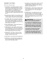
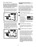
HOW TO PLUG IN THE POWER CORD 

Your treadmill, like any other type of sophisticated
electronic equipment, can be seriously damaged by
sudden voltage changes in your home’s power.
Voltage surges, spikes, and noise interference can 
result from weather conditions or from other appliances
being turned on or off. To decrease the possibility of
your treadmill being damaged, always use a surge
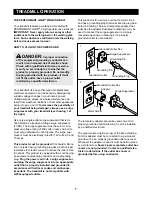
suppressor with your treadmill (see drawing 1 at
the right).

Use only a single-outlet surge suppressor that is UL
1449 listed as a transient voltage surge suppressor
(TVSS). The surge suppressor must have a UL sup-
pressed voltage rating of 400 volts or less and a mini-
mum surge dissipation of 450 joules. The surge sup-
pressor must be electrically rated for 120 volts AC and
15 amps.

This product must be grounded. If it should malfunc-
tion or break down, grounding provides a path of least
resistance for electric current to reduce the risk of elec-
tric shock. This product is equipped with a cord having
an equipment-grounding conductor and a grounding
plug. Plug the power cord into a surge suppressor,
and plug the surge suppressor into an appropriate
outlet that is properly installed and grounded in
accordance with all local codes and ordinances.
Important: The treadmill is not compatible with
GFCI-equipped outlets.

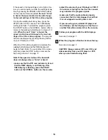
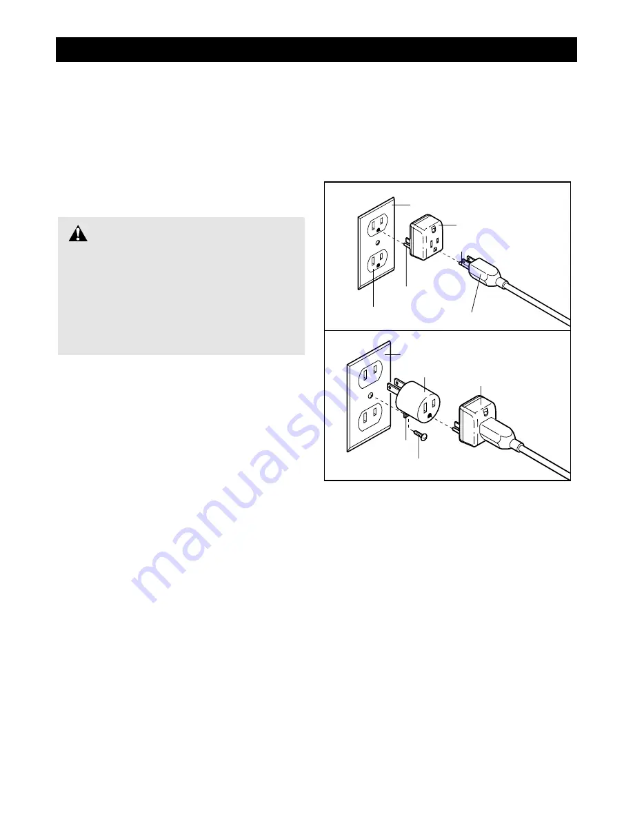
This product is for use on a nominal 120-volt circuit,
and has a grounding plug that looks like the plug illus-
trated in drawing 1 below. A temporary adapter that
looks like the adapter illustrated in drawing 2 may be
used to connect the surge suppressor to a 2-pole 
receptacle as shown in drawing 2 if a properly 
grounded outlet is not available. 

The temporary adapter should be used only until a
properly grounded outlet (drawing 1) can be installed
by a qualified electrician. 

The green-colored rigid ear, lug, or the like extending
from the adapter must be connected to a permanent
ground such as a properly grounded outlet box cover.
Whenever the adapter is used it must be held in place
by a metal screw. Some 2-pole receptacle outlet box
covers are not grounded. Contact a qualified elec-
trician to determine if the outlet box cover is
grounded before using an adapter.

DANGER:

Improper connection

of the equipment-grounding conductor can
result in an increased risk of electric shock.
Check with a qualified electrician or service-
man if you are in doubt as to whether the
product is properly grounded. Do not modify
the plug provided with the product—if it will
not fit the outlet, have a proper outlet 
installed by a qualified electrician.

1

2

Grounded Outlet Box

Grounded Outlet Box

Grounding Plug

Surge Suppressor

Surge Suppressor

Grounding Pin

Adapter

Lug

Metal Screw

Grounded Outlet

Grounding Pin

Summary of Contents for RBTL10500

Page 1: ...viding complete customer satisfaction If you have questions or if there are missing or damaged parts we will guarantee complete satisfac tion through direct assistance from our factory TO AVOID UNNECESSARY DE LAYS PLEASE CALL DIRECT TO OUR TOLL FREE CUSTOMER HOT LINE The trained techni cians on our Customer Hot Line will provide immediate assis tance free of charge to you CUSTOMER HOT LINE 1 800 9...

Page 2: ... UNIVERSITY 26 EXERCISE GUIDELINES 28 PART LIST 30 HOW TO ORDER REPLACEMENT PARTS 31 LIMITED WARRANTY Back Cover Note An EXPLODED DRAWING is attached in the center of this manual TABLE OF CONTENTS REEBOK and the Vector Logo are registered trademarks and service marks of Reebok This product is manufactured and distributed under license from Reebok International ...

Page 3: ...sion cord 13 Use only a single outlet surge suppressor that is UL 1449 listed as a transient voltage surge suppressor TVSS The surge suppressor must have a UL suppressed voltage rating of 400 volts or less and a minimum surge dissi pation of 450 joules The surge suppressor must be electrically rated for 120 volts AC and 15 amps 14 Keep the power cord and the surge suppres sor away from heated surf...

Page 4: ...ing 29 DANGER Always unplug the power cord immediately after use before cleaning the treadmill and before performing the main tenance and adjustment procedures de scribed in this manual Never remove the motor hood unless instructed to do so by an authorized service representative Servicing other than the procedures in this manual should be performed by an authorized service representative only WAR...

Page 5: ...r Customer Service Department toll free at 1 800 999 3756 Monday through Friday 6 a m until 6 p m Mountain Time excluding holidays To help us assist you please mention the product model number and serial number when calling The model number is RBTL10500 The serial number can be found on a decal attached to the treadmill see the front cover of this manual for the location Before reading further ple...

Page 6: ...included with the heart rate monitor 1 Remove the eight indicated Screws 66 from the back of the Console Base 80 2 Lift the Console 81 as shown be careful not to pull any wires Peel the paper off the pad on the back of the Receiver A Turn the Receiver so the cylinder is on the side shown and press the Receiver into the bottom of the Console Base 80 in the indicated location Next connect the Jumper...

Page 7: ...and plug the surge suppressor into an appropriate outlet that is properly installed and grounded in accordance with all local codes and ordinances Important The treadmill is not compatible with GFCI equipped outlets This product is for use on a nominal 120 volt circuit and has a grounding plug that looks like the plug illus trated in drawing 1 below A temporary adapter that looks like the adapter ...

Page 8: ...e available sep arately iFIT com CD programs automatically control the speed and incline of the treadmill as a personal trainer guides you through every step of your workout High energy music provides added motivation Each CD features two programs designed by certified per sonal trainers In addition you can connect the treadmill to your VCR and TV and play iFIT com video programs videocas settes a...

Page 9: ... workout programs custom programs and the iFIT com mode G START Button This button starts the walking belt H STOP Button This button stops the walking belt When the button is pressed the LED displays will pause and the TIME display will flash I Key with Clip The key turns the console on and off The attached clip is designed to be worn on your waistband If the key is pulled from the console the pow...

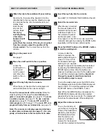
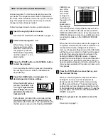
Page 10: ...WER at the left Select the manual mode When the key is inserted the manual mode will be selected and the manual indicator will light If you have selected a preset workout program a cus tom program or the iFIT com mode select the manual mode again by pressing the MODE button repeatedly until the manual indicator lights Press the START button or the SPEED button to start the walking belt A moment af...

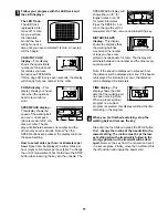
Page 11: ... the console The SPEED PACE display will show either an E for English miles or an M for metric kilometers Press the SPEED but ton to change the unit of measurement Then remove and reinsert the key DISTANCE LAPS display This display shows the distance that the walking belt has moved and the number of laps you have com pleted one lap equals 1 4 mile The display will alternate between one number and ...

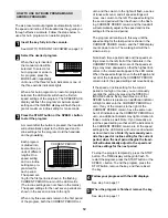
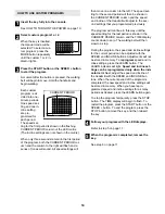
Page 12: ...utomatically adjust to the speed and incline settings for the second period The program will continue in this way until the speed setting for the last period is shown in the CURRENT PERIOD column and the TIME display counts down to zero The walking belt will then slow to a stop Note Each time a period ends and the speed set tings move to the left if all of the indicators in the CURRENT PERIOD colu...

Page 13: ...s are not shown in the matrix To program speed and in cline settings for the first period simply adjust the speed and in cline of the treadmill to the desired levels with the SPEED and INCLINE buttons Every few times the SPEED buttons are pressed one additional indica tor will light or darken in the CURRENT PERIOD column When the first one minute period of the program is completed a series of tone...

Page 14: ...tings that you programmed previously The program will continue in this way until the speed setting for the last period is shown in the CURRENT PERIOD column and the TIME display counts down to zero The walking belt will then slow to a stop During the program the speed and incline settings for the current period can be adjusted with the SPEED and INCLINE buttons Adjustments will not be stored in me...

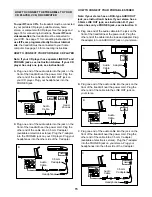
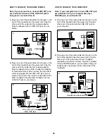
Page 15: ...able at electronics stores Plug the Y adapter into the PHONES jack on your CD player Plug your headphones into the other side of the Y adapter HOW TO CONNECT YOUR PORTABLE STEREO Note If your stereo has an RCA type AUDIO OUT jack see instruction A below If your stereo has a 3 5mm LINE OUT jack see instruction B If your stereo has only a PHONES jack see instruction C A Plug one end of the audio cab...

Page 16: ... RCA Y adapter Plug the RCA Y adapter into the LINE OUT jack on your stereo HOW TO CONNECT YOUR COMPUTER Note If your computer has a 3 5mm LINE OUT jack see instruction A If your computer has only a PHONES jack see instruction B A Plug one end of the audio cable into the jack on the front of the treadmill near the power cord Plug the other end of the cable into the LINE OUT jack on your computer B...

Page 17: ...steps below to use an iFIT com CD or video program Insert the key fully into the console See HOW TO TURN ON THE POWER on page 10 Select the iFIT com mode When the key is in serted the manual mode will be selected To use an iFIT com CD or video program press the MODE button re peatedly until the iFIT com indicator lights The let ters i Fit and three moving indicators will appear in the LED matrix I...

Page 18: ...in to flash Note To use another CD or video program press the STOP button or remove the key and go to step 1 on page 17 Note If the speed or incline of the treadmill does not change when a chirp is heard make sure that the iFIT com indicator is lit and that the TIME display is not flashing If the TIME display is flashing press the START button or the SPEED button on the console adjust the volume o...

Page 19: ...n screen count down will begin Return to the treadmill and stand on the foot rails Find the clip attached to the key and slide the key onto the waistband of your clothing When the on screen countdown ends the program will begin and the walking belt will begin to move Hold the handrails step onto the walking belt and begin walking During the program an electronic chirping sound will alert you when ...

Page 20: ...his mode is intended to be used only when a treadmill is displayed in a store When the console is in the demo mode the power cord can be plugged in the key can be removed from the console and the displays and indicators on the console will auto matically light in a preset sequence although the but tons on the console will not operate If a d appears in the CALS FAT CALS display when the information...

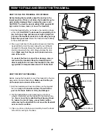
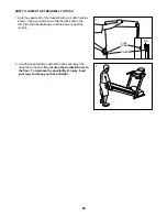
Page 21: ...he lock knob Make sure that the pin on the lock knob is in side of the catch To protect the floor or carpet from damage place a mat under the treadmill Keep the treadmill out of direct sunlight Do not leave the treadmill in the stor age position in temperatures above 85 Fahrenheit HOW TO MOVE THE TREADMILL Before moving the treadmill convert the treadmill to the stor age position as described abov...

Page 22: ...d slide the lock knob to the left Pivot the treadmill down until the frame is past the lock pin 2 Hold the treadmill firmly with both hands and lower the treadmill to the floor Do not drop the treadmill frame to the floor To decrease the possibility of injury bend your legs and keep your back straight Lock Knob Catch Pin 1 2 ...

Page 23: ...ircuit breaker has tripped wait for five minutes and then press the switch back in b Make sure that the power cord is plugged in c Remove the key from the console Reinsert the key into the console as far as it will go d Make sure that the on off switch is in the on position e If the treadmill still will not run please call our Customer Service Department toll free PROBLEM The Speed Minutes Mile di...

Page 24: ...n the power cord insert the key and run the treadmill for a few minutes Repeat until the walking belt is centered b If the walking belt has shifted to the right first remove the key and UNPLUG THE POWER CORD Using the allen wrench turn the left rear roller adjustment bolt counterclockwise and the right bolt clockwise 1 4 of a turn each Be careful not to overtighten the walking belt Plug in the pow...

Page 25: ...os are played SOLUTION a With the key in the console press one of the INCLINE buttons While the incline is changing remove the key After a few seconds re insert the key The treadmill will automatically rise to the maximum incline level and then return to the minimum level This will recalibrate the incline system ...

Page 26: ...cholesterol from the body and can lower concentrations of blood triglyc erides a storage form of fat thus reducing the risk for cardiovascular disease Duncan and his colleagues3 concluded that exercise does not have to be vigorous to reduce cardiovascular risk factors In other words people who choose to stroll rather than walk briskly can reduce their risk for cardiovascular disease After studying...

Page 27: ...er hour sustained a walking related injury that necessitated consulting with a physician Carroll and his colleagues10 reported that 14 of the elderly sub jects participating in a walking study suffered training related orthopedic injuries mostly to the lower leg and foot The majority of injuries occurred in the group as signed to fast walking It is important to note that all forms of exercise have...

Page 28: ...ntil your heart rate is near the lowest number in your training zone For maximum fat burning adjust the speed or incline of the treadmill until your heart rate is near the middle number in your training zone Aerobic Exercise If your goal is to strengthen your cardiovascular sys tem your exercise must be aerobic Aerobic exercise is activity that requires large amounts of oxygen for pro longed perio...

Page 29: ...illes Stretch With one leg in front of the other reach forward and place your hands against a wall Keep your back leg straight and your back foot flat on the floor Bend your front leg lean forward and move your hips toward the wall Hold for 15 counts then relax Repeat 3 times for each leg To cause further stretching of the achilles tendons bend your back leg as well Stretches Calves achilles tendo...

Page 30: ...0 4 Isolator Nut 51 1 Heart Rate Strap 52 4 Roller Adj Washer 53 2 Rear Roller Adjustment Bolt 54 1 Rear Endcap 55 1 Frame 56 1 Allen Wrench 57 2 Rear Platform Screw 58 1 Rear Roller 59 1 Motor Assembly 60 1 Motor Pivot Nut 61 3 Nylon Washer 62 1 Foam Grip left 63 1 Motor Tension Bolt 64 1 Motor Tension Nut 65 1 Upright 66 6 Console Screw 67 1 Lock Knob 68 1 Lock Knob Sleeve 69 1 Lock Knob Spring ...

Page 31: ... s Manual Includes all parts shown in the box For information about the optional heart rate monitor see page 20 These parts are not illustrated Key No Qty Description Key No Qty Description To order replacement parts call our Customer Service Department toll free at 1 800 999 3756 Monday through Friday 6 a m until 6 p m Mountain Time excluding holidays To help us assist you please be prepared to g...

Page 32: ...nts specified in the Manual to assure proper operation and your continued satisfac tion HOW TO GET PARTS AND SERVICE Simply call our Customer Service Department at 1 800 999 3756 and tell them your name and address and the serial number of your Product They will tell you how to get a part replaced or if necessary arrange for service where your Product is located or advise you how to ship the Produ...

Page 33: ... 43 44 44 43 53 52 54 53 52 43 48 57 55 56 58 44 90 49 50 49 50 49 50 49 50 43 13 14 15 17 26 18 30 31 99 100 101 103 102 36 33 34 35 99 99 26 27 99 37 15 14 13 3 26 27 27 26 26 19 26 27 40 40 43 42 38 111 16 115 110 30 61 29 64 32 22 24 79 59 63 112 112 60 60 113 EXPLODED DRAWING MODEL NO RBTL10500 R1200A ...

Page 34: ...6 78 77 73 13 13 98 99 82 13 76 77 78 98 99 73 13 86 87 87 91 31 93 30 94 95 97 96 105 106 107 104 85 51 43 43 92 109 108 23 83 66 80 83 108 66 66 66 88 88 81 108 108 108 25 111 20 104 EXPLODED DRAWING MODEL NO RBTL10500 R1200A ...

Reviews: