background image

1

1

Left Foot Rail

2

1

Right Foot Rail

3*

1

Idler Assembly

4

4

Isolator

5

1

Latch Catch

6

1

Platform

7

4

Walking Deck Screw

8

1

Walking Belt

9

2

Frame Pivot Bolt

10

1

Latch Assembly

11

1

Front Roller/Pulley

12

1

Magnet

13

9

Front Wheel Nut/
Pivot Nut

14

2

Spacer Insert

15

2

Frame Pivot Spacer

16

1

Reed Switch Clip

17

1

Reed Switch

18

1

Lift Frame

19

4

Wire Clip

20

1

Idler Arm

21

2

Pulse Bar Bolt

22

1

Motor Belt

23

1

Idler Pulley

24

1

Motor

25

1

Pulley Spacer

26

2

Static Warning Decal

27

4

Hood Bracket

28

1

Pulley Nut

29

1

Idler Spring

30

1

Chest Pulse Sensor

31

1

Lift Motor Bolt

32

2

Motor Bolt

33

1

Outlet Bracket  

34

4

Plastic Stand-off

35

1

Power Supply

36

1

Power Supply Bracket

37

1

Controller

38

1

Controller Bracket

39

1

Motor Hood

40

6

Latch Catch Screw/
Rear Endcap Screw

41

1

Motor Belly Pan

42

2

Belt Guide

43

21

Misc. Screw

44

13

Plastic Fastener

45

1

Frame Belly Pan

46

1

Pulse Bar

47

1

Ground Wire

48

2

Rear Foot

49

4

Isolator Washer

50

4

Isolator Nut

51

1

Chest Pulse Strap

52

2

Roller Adj. Washer

53

2

Rear Roller Adj. Bolt

54

1

Rear Endcap

55

1

Frame

56

1

Allen Wrench

57

2

Rear Platform Screw

58

1

Rear Roller

59

1

Pulse Wire Harness

60

1

Filter Wire

61

1

Book Rack

62

1

Left Foam Grip

63

2

Handrail Endcap

64

1

Pulse Sensor

65

1

Upright

66

4

Base Mounting Screw

67

1

Lock Knob

68

2

Roller Star Washer

69

1

Lock Knob Spring

70

1

Lock Pin Collar

71

1

Pin Clip

72

1

Lock Pin

73

2

Incline Pivot Bolt

74

1

Wire Harness 
Grommet

75

8

Console Screw

76

4

Frame Pivot Washer

77

2

Front Wheel

78

2

Wheel Bolt

79

1

Right Foam Grip

80

1

Console Base (Top)

81

1

Console

82

1

Key/Clip

83

1

Console Base (Bottom)

84

1

Pulse Sensor Plate

85

1

Upright Wire Harness

86

1

Shock

87

2

Upright Endcap

88

5

Pulley Washer/
Wheel Washer

89

1

Pulse Sensor Cover

90

1

Latch Warning Decal

91

1

Incline Motor

92

1

Controller Wire

93

4

Front Belly Pan Screw

94

6

Sensor Cover Screw/
Rear Foot

95

2

Tie Holder

96

2

Tie

97

5

8” Cable Tie

98

4

Bumper

99

4

Bumper Screw

100

1

On/Off Switch

101

1

Circuit Breaker

102

1

Power Cord

103

1

Power Cord Grommet

104

2

Warning Decal

105

20

Foot Rail Screw

106

1

Jack

107

1

iFIT.com Audio Cable

108

14

Foam Grip Screw/
Belt Guide Screw

109

2

2-pound Weight

110

2

Foam Pad

111

1

12” Audio Wire

112

1

Tension Washer

113

1

Tension Bolt

114

4

Motor Mounting 
Washer

115

1

Console Ground Wire

116

1

Motor Plate

117

2

Motor Isolator

118

1

Audio Wire Nut

119

2

Outlet Bracket 
Star Washer

120

4

Controller Screw

121

1

Lift Motor Screw/
Base Screw

122

7

Hood Screw/Foam 
Grip Screw

123

3

Long Console Screw

124

1

Idler Pulley Bolt

#

1

14” White Wire, 2 F

#

1

8” White Wire, M/F

#

1

8” Blue Wire, 2 F

#

1

8” Blue Wire, M/F

#

1

4” Black Wire, 2 F

#

1

12” Green Wire, F/R

#

1

User’s Manual

* Includes all parts shown in the box
# These parts are not illustrated 

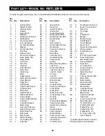
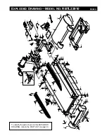
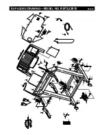
To locate the parts listed below, refer to the EXPLODED DRAWING attached in the center of this manual.

Key 

No.

Qty.

Description

Key 

No.

Qty.

Description

Key 

No.

Qty.

Description

30

P

ART

L

IST

—M

ODEL

N

O.

RBTL22910                             

R0402A

Summary of Contents for RBTL22910

Page 1: ...If you have questions or if there are missing parts we will guar antee complete satisfaction through direct assistance from our factory TO AVOID UNNECESSARY DELAYS PLEASE CALL DIRECT TO OUR TOLL FREE CUSTOMER HOT LINE The trained techni cians on our customer hot line will provide immediate assis tance free of charge CUSTOMER HOT LINE 1 800 999 3756 Mon Fri 6 a m 6 p m MST Visit our website at www ...

Page 2: ...5 REEBOK UNIVERSITY 27 EXERCISE GUIDELINES 29 PART LIST 30 HOW TO ORDER REPLACEMENT PARTS 31 LIMITED WARRANTY Back Cover Note An EXPLODED DRAWING is attached in the center of this manual TABLE OF CONTENTS REEBOK and the Vector Logo are registered trademarks and service marks of Reebok This product is manufactured and distributed under license from Reebok International ...

Page 3: ...ur local REEBOK dealer or call 1 800 806 3651 and order part number 146148 11 Keep the power cord and the surge suppres sor away from heated surfaces 12 Failure to use a properly functioning surge suppressor could result in damage to the con trol system of the treadmill If the control sys tem is damaged the walking belt may change speed or stop unexpectedly which may result in a fall and serious i...

Page 4: ...ning the treadmill and before performing the main tenance and adjustment procedures de scribed in this manual Never remove the motor hood unless instructed to do so by an authorized service representative Servicing other than the procedures in this manual should be performed by an authorized service representative only 27 The treadmill is intended for in home use only Do not use the treadmill in a...

Page 5: ...ustomer Service Department toll free at 1 800 999 3756 Monday through Friday 6 a m until 6 p m Mountain Time excluding holidays To help us assist you please note the product model number and serial number before calling The model number is RBTL22910 The serial number can be found on a decal attached to the treadmill see the front cover of this manual for the location Before reading further please ...

Page 6: ...asive cleaner 1 With the help of a second person carefully raise the Uprights 65 until the Wheels 77 are resting on the floor as shown 1 77 65 2 Remove the Lock Knob 67 from the Lock Pin 72 Make sure that the Lock Pin Collar 70 and the Spring 69 are on the Lock Pin Note If there are two Lock Pin Collars there should be one on each side of the Spring Insert the Lock Pin through the Left Foam Grip 6...

Page 7: ...er that may trap moisture Do not expose the chest pulse sensor to direct sunlight for extended periods of time do not expose it to temperatures above 122 Fahrenheit 50 Celsius or below 14 Fahrenheit 10 Celsius Do not excessively bend or stretch the sensor unit when using or storing the chest pulse sensor Clean the sensor unit using a damp cloth never use alcohol abrasives or chemicals The chest st...

Page 8: ...t resistance for electric current to reduce the risk of elec tric shock This product is equipped with a cord having an equipment grounding conductor and a grounding plug Plug the power cord into a surge suppressor and plug the surge suppressor into an appropriate outlet that is properly installed and grounded in accordance with all local codes and ordinances Important The treadmill is not compatib...

Page 9: ... treadmill to your home stereo portable stereo or computer and play special iFIT com CD programs iFIT com CDs are avail able separately IFIT com CD programs automatically control the speed and incline of the treadmill as a per sonal trainer guides you through every step of your workout High energy music provides added motivation Each CD features two programs designed by certified personal trainers...

Page 10: ...pper body exercise to your workouts M Pulse display When the handgrip pulse sensor or the chest pulse sensor is used this display will show your heart rate N Calories display This display shows the approxi mate numbers of calories and fat calories you have burned see Fat Burning on page 29 The display will alternate between one number and the other every seven seconds O Distance Incline display Th...

Page 11: ...r the OneTouch Speed buttons Note After the buttons are pressed it may take a moment for the walking belt to reach the selected speed setting To stop the walking belt press the Stop button The displays will pause and the Time Segment Time display will begin to flash To restart the walking belt press the Start button or the Speed button To stop the walking belt and reset the dis plays press the Sto...

Page 12: ...ternate between one number and the other every seven seconds Distance Incline display This display shows the distance you have walked and the incline level of the tread mill The display will al ternate between one number and the other every seven seconds Note Each time the Incline buttons are pressed the dis play will change to show the incline setting Speed display This display shows the speed of...

Page 13: ...right will flash and a tone will sound In addition if the speed and or incline of the treadmill is about to change the Speed display and or the Distance Incline display will flash to alert you and three tones will sound When the first segment is completed all speed settings will move one column to the left The speed setting for the second segment will then be shown in the flashing Current Segment ...

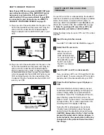
Page 14: ...le See HOW TO TURN ON THE POWER on page 11 Put on the chest pulse sensor To use a pulse program you must wear the chest pulse sensor Refer to page 7 for instruc tions Select one of the two pulse programs When the key is inserted the manual mode will be selected To select one of the pulse programs press the Select Workout button repeatedly until one of the two pulse program indi cators lights The p...

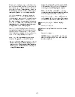
Page 15: ... only three seconds remain in the first seg ment of the program both the Current Segment column and the column to the right will flash a se ries of tones will sound and the Speed display and the Distance Incline display will flash When the first segment is completed all heart rate set tings will move one column to the left The heart rate setting for the second segment will then be shown in the fla...

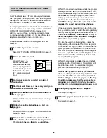
Page 16: ...the Speed and Incline buttons Every few times one of the Speed buttons is pressed an additional indicator will light or darken in the Current Segment column When the first segment of the program is com pleted the current speed setting and the current incline setting will be stored in memory The three columns of indicators will then move one column to the left and the speed setting for the second s...

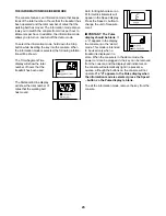
Page 17: ...l then be shown in the flashing Current Segment column and the treadmill will automatically adjust to the speed and incline settings for the second seg ment The program will continue until the speed setting for the final segment is shown in the Current Segment column and no time remains in the Time Segment Time display The walking belt will then slow to a stop If desired you can redefine to the pr...

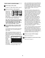
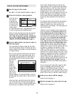
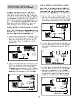
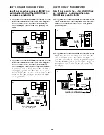
Page 18: ...at electronics stores Plug the Y adapter into the PHONES jack on your CD player Plug your headphones into the other side of the Y adapter HOW TO CONNECT YOUR PORTABLE STEREO Note If your stereo has an RCA type AUDIO OUT jack see instruction A below If your stereo has a 3 5mm LINE OUT jack see instruction B If your stereo has only a PHONES jack see instruction C A Plug one end of the audio cable in...

Page 19: ... the Y adapter Plug the Y adapter into the LINE OUT jack on your stereo HOW TO CONNECT YOUR COMPUTER Note If your computer has a 3 5mm LINE OUT jack see instruction A If your computer has only a PHONES jack see instruction B A Plug one end of the audio cable into the jack on the front of the treadmill near the power cord Plug the other end of the cable into the LINE OUT jack on your computer B Plu...

Page 20: ...ll free 1 800 735 0768 Follow the steps below to use an iFIT com CD or video program Insert the key into the console See HOW TO TURN ON THE POWER on page 11 Select the iFIT com mode When the key is in serted the manual mode will be selected To use iFIT com CDs or videocassettes press the iFIT com button The iFIT com indicator will light Insert the iFIT com CD or videocassette If you are using an i...

Page 21: ...or video program press the Stop button or re move the key and go to step 1 on page 20 Note If the speed or incline of the treadmill does not change when a chirp is heard Make sure that the iFIT com indicator is lit and that the Time Segment Time display is not flashing If the Time Segment Time display is flashing press the Start button or the Speed button on the console Adjust the volume of your C...

Page 22: ...l begin and the walking belt will begin to move Hold the handrails step onto the walking belt and begin walking During the program an electronic chirping sound will alert you when the speed and or incline of the treadmill is about to change CAUTION Always listen for the chirp and be prepared for speed and or incline changes If the speed or incline settings are too high or too low you can manually ...

Page 23: ... used The Distance Incline display will show the total number of miles that the walking belt has moved An E for English miles or an M for metric kilometers will appear in the Speed display Press the Speed button to change the unit of measure ment IMPORTANT The Pulse display should be blank If a d appears in the display the console is in the demo mode This mode is intended to be used only when a tr...

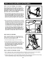
Page 24: ...he treadmill Keep the treadmill out of direct sunlight Do not leave the treadmill in the stor age position in temperatures above 85 Fahrenheit HOW TO MOVE THE TREADMILL Before moving the treadmill convert the treadmill to the storage position as described above Make sure that the latch pin is securely holding the catch 1 Hold the handrails and place one foot on the base 2 Tilt the treadmill back u...

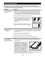
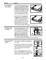
Page 25: ...einsert it d Make sure that the on off switch is in the on position see 1 d above a Use only a single outlet surge suppressor that meets all of the specifications de scribed on page 8 b If the walking belt is overtightened tread mill performance may decrease and the walking belt may be permanently dam aged Remove the key and UNPLUG THE POWER CORD Using the included allen wrench turn both rear roll...

Page 26: ...ve the hood Locate the Reed Switch 17 and the Magnet 12 on the left side of the Pulley 11 Turn the Pulley until the Magnet is aligned with the Reed Switch Make sure that the gap between the Magnet and the Reed Switch is about 1 8 If necessary loosen the Screw 43 and move the Reed Switch slightly Retighten the Screw Re attach the hood and run the treadmill for a few minutes to check for a correct s...

Page 27: ...ich removes excess cholesterol from the body and can lower concentrations of blood triglyc erides a storage form of fat thus reducing the risk for cardiovascular disease Duncan and his colleagues3 concluded that exercise does not have to be vigorous to reduce cardiovascular risk factors In other words people who choose to stroll rather than walk briskly can reduce their risk for cardiovascular dis...

Page 28: ...er hour sustained a walking related injury that necessitated consulting with a physician Carroll and his colleagues10 reported that 14 of the elderly sub jects participating in a walking study suffered training related orthopedic injuries mostly to the lower leg and foot The majority of injuries occurred in the group as signed to fast walking It is important to note that all forms of exercise have...

Page 29: ...ular sys tem your exercise must be aerobic Aerobic exercise is activity that requires large amounts of oxygen for prolonged periods of time This increases the demand on the heart to pump blood to the muscles and on the lungs to oxygenate the blood For aerobic exercise adjust the speed or incline of the treadmill until your heart rate is near the highest number in your training zone WORKOUT GUIDELI...

Page 30: ...in Clip 72 1 Lock Pin 73 2 Incline Pivot Bolt 74 1 Wire Harness Grommet 75 8 Console Screw 76 4 Frame Pivot Washer 77 2 Front Wheel 78 2 Wheel Bolt 79 1 Right Foam Grip 80 1 Console Base Top 81 1 Console 82 1 Key Clip 83 1 Console Base Bottom 84 1 Pulse Sensor Plate 85 1 Upright Wire Harness 86 1 Shock 87 2 Upright Endcap 88 5 Pulley Washer Wheel Washer 89 1 Pulse Sensor Cover 90 1 Latch Warning D...

Page 31: ...m until 6 p m Mountain Time excluding holidays To help us assist you please be prepared to give the following information The MODEL NUMBER of the product RBTL22910 The NAME of the product REEBOK RX 5000 treadmill The SERIAL NUMBER of the product see the front cover of this manual The KEY NUMBER and DESCRIPTION of the part s see the PART LIST on page 30 ...

Page 32: ...ce requirements specified in the Manual to assure proper operation and your continued satisfac tion HOW TO GET PARTS AND SERVICE Simply call our Customer Service Department at 1 800 999 3756 and tell them your name and address and the serial number of your Product They will tell you how to get a part replaced or if necessary arrange for service where your Product is located or advise you how to sh...

Page 33: ...5 56 58 44 90 111 49 50 49 50 49 50 40 43 27 27 43 43 19 43 27 32 22 24 3 114 114 93 41 93 93 122 39 122 122 4 49 50 20 88 29 25 28 23 13 124 113 26 118 5 32 117 116 40 42 108 105 105 105 105 105 105 68 68 76 114 76 114 76 76 112 43 60 120 37 119 EXPLODED DRAWING MODEL NO RBTL22910 R0402A To identify the parts shown on this EXPLODED DRAWING refer to the PART LIST on page 30 ...

Page 34: ...5 75 75 75 84 61 81 123 123 94 123 63 62 67 46 79 69 70 72 71 109 86 77 77 104 73 13 78 13 73 13 13 78 99 98 99 98 99 98 98 99 87 87 65 63 85 122 122 26 10 21 21 59 115 43 88 88 88 88 104 110 110 94 30 94 89 EXPLODED DRAWING MODEL NO RBTL22910 R0402A ...

Reviews: