background image

10

PowerMast by ReechCraft

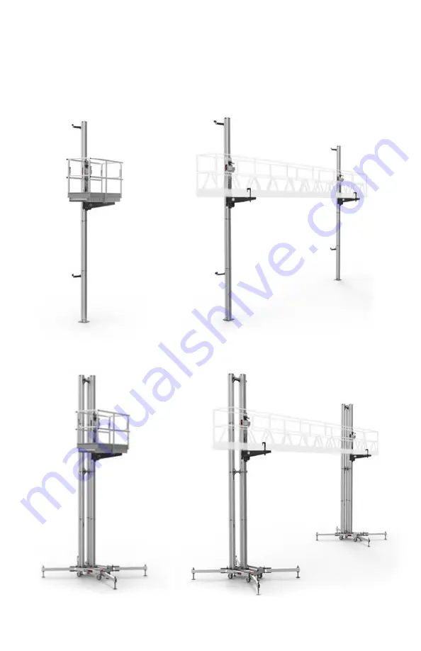
Figure 1.0 

- Wall-tied System Configuration - Single Mast/ Twin Mast

Figure 1.1 

-


Freestanding System Configuration - Single Mast/Twin Mast

SECTION 1

GENERAL SYSTEM INFORMATION

1.0

  System Configurations

Summary of Contents for PowerMAST

Page 1: ...OPERATOR S SAFETY MANUAL 4026288...

Page 2: ...d without prior written permission from ReechCraft Inc Product General Information Model PowerMast This is the Safety Alert Symbol It is used on the machine to alert you to potential personal injury h...

Page 3: ...REECHCRAFT TO ENSURE THAT THE CURRENT OWNER RECORDS ARE UPDATED AND ACCURATE REECHCRAFT MUST BE NOTIFIED IMMEDIATELY IN ALL INSTANCES WHERE OUR PRODUCTS HAVE BEEN INVOLVED IN AN ACCIDENT INVOLVING BO...

Page 4: ...istance of the platform to the wall or structure taking into consideration wall offsets curves balconies architectural features trees wires etc 6 Be aware of and refer to federal state and local guide...

Page 5: ...led in this manual consult with the ReechCraft engineering team 14 Always keep hands limbs and clothing a safe distance from any moving parts 15 Be sure all switches are off before connecting any elec...

Page 6: ...ssembly 13 1 4 Wall tied System Assembly 14 1 5 Specifications 15 1 6 Wall tied System Configuration 16 1 7 Freestanding System Configuration 18 SECTION 2 LAYOUT PLANNING 2 0 Layout Planning 20 2 1 Gr...

Page 7: ...6160 7 SECTION 5 OPERATINGTHE SYSTEM 5 0 Operating the Work Platform 44 SECTION 6 TRANSPORT STORAGE 6 0 Transport Storage 46 Transport 46 Storage 46 SECTION 7 INSPECTION MAINTENANCE 7 0 Inspection Mai...

Page 8: ...8 Wall tied System Configuration 17 1 9 Freestanding System Configuration 19 2 0 Wall tied System Configuration Examples 22 2 1 Loading the Mast 22 2 2 Extending the Mast 23 2 3 Securing the Base 23 2...

Page 9: ...Erecting the Freestanding System 38 4 0 Driver Installation 40 4 1 Drill Installation 41 4 2 Adjusting the Drill 41 4 3 Securing the Cords 42 4 4 Cord Management 42 4 5 Power Cord Installation 43 5 0...

Page 10: ...st by ReechCraft Figure 1 0 Wall tied System Configuration Single Mast Twin Mast Figure 1 1 Freestanding System Configuration Single Mast Twin Mast SECTION 1 GENERAL SYSTEM INFORMATION 1 0 System Conf...

Page 11: ...0 11 GENERAL SYSTEM INFORMATION Figure 1 2 Climbing Unit SECTION 1 Overspeed Brake Platform Hold Down Assembly Gearbox 3 8 in Nut Driver Drill Bracket with Adjustable Lock Collar Lock Lever 1 1 Climbi...

Page 12: ...12 PowerMast by ReechCraft GENERAL SYSTEM INFORMATION 5 ft 1 5 m Mast Section Base Figure 1 3 Wall tied System Base SECTION 1 1 2 Mast Base Assembly...

Page 13: ...com powermast 888 600 6160 13 GENERAL SYSTEM INFORMATION Rear Hold Down Bracket SECTION 1 1 3 Platform Support Assembly Figure 1 4 Freestanding System Base Figure 1 5 Platform Support Assembly Platfo...

Page 14: ...PowerMast by ReechCraft GENERAL SYSTEM INFORMATION Wall tie Mount Adjustable Bracket Extension Tube SECTION 1 1 4 Wall tied System Assembly Figure 1 6 Wall tied System Assembly Figure 1 7 Tri mast Ti...

Page 15: ...load Clutch and Overspeed Brake Emergency Lowering Manual Descent Crank Available Mast ConnectionType Interference Locking Cam Lever Drive System 120 1 Clutch ProtectedTransmission Required Voltage 11...

Page 16: ...der Rated Load G Mast Clearance Standard Tie 6 16 5 in 152 419 mm H Maximum Platform Height 194 ft 59 1 m I Maximum Platform Height Above Lower Tie During Use Single Mast Tied 0 ft 0 m Twin Mast Tied...

Page 17: ...reechcraft com powermast 888 600 6160 17 GENERAL SYSTEM INFORMATION D F B G B C H K I J E Figure 1 8 Wall tied System Configuration SECTION 1 A G...

Page 18: ...05 mm D Outrigger Depth Standard 101 in 2565 mm E Platform Clearance Mast Side Standard 49 7 in 1262 mm F Platform Clearance Gearbox Side Standard 25 in 635 mm Retraction 0 in 0 mm G Outrigger Width R...

Page 19: ...reechcraft com powermast 888 600 6160 19 GENERAL SYSTEM INFORMATION Figure 1 9 Freestanding System Configuration SECTION 1 E F H I J A B G K C D...

Page 20: ...340 kg rated load on each climbing unit Mast locations What is the mast distance from the wall Will there be any special provisions for ground support needed Wall tied system locations 18 feet 5 5 met...

Page 21: ...ions to ensure the surface can support the intended load of the system Prepare the base surface for erection removing any debris obstacles or any other conditions that could lead to injury during erec...

Page 22: ...ee Figure 2 0 2 2 Wall tied System Planning Table 2 2 Wall tied System Requirements DESCRIPTION SPECIFICATION MaximumTie Spacing 18 ft 5 5 m Total Tie Pull out Force 1500 lbs Total 750 lbs perTie Arm...

Page 23: ...ng that the track is aligned and facing toward the platform 3 Press both cam levers down and in at the same time 2 Rotate the cam lever lock until it stops in the center position 4 Be sure the cam lev...

Page 24: ...d for erection Be sure all components have been inspected and maintained in accordance with product labels on the unit information contained in this manual and any other documents supplied by the Reec...

Page 25: ...he tie vertically if necessary 4 Move the mast to the desired position and tighten the extension tube bolts 5 Fully secure every bolt connection on the tie before proceeding Figure 3 1 Anchoring the T...

Page 26: ...the base See Figure 3 2 To assemble the platform support rotate the pins up and remove See Figure 3 3 Figure 3 2 Erecting the Base Unit Figure 3 3 Assembling the Platform Support Anchor Point No Rotat...

Page 27: ...THE SYSTEM SECTION 3 Measure the platform bottom to the midrail top Position the support so the top rail is just below the gearbox See Figure 3 4 Figure 3 4 Positioning the Platform Support Midrail T...

Page 28: ...he platform support s See Figures 3 5 and 3 6 Figure 3 5 Attaching the Platform to the Supports Single Mast Figure 3 6 Attaching the Platform to the Supports Twin Mast 3 ERECTING THE SYSTEM SECTION 3...

Page 29: ...o the platform moves side to side up to two inches to allow for a temporary 10 degree angle for emergency one operator descent Be sure the platform only moves slightly side to side but does not lift o...

Page 30: ...e platform approximately three inches 76 2 mm below the top of the mast Connect the masts See Figures 2 4 and 3 8 Note Refer to Section 4 0 for power system installation Figure 3 8 Connecting the Mast...

Page 31: ...0 31 3 ERECTING THE SYSTEM SECTION 3 Fasten the ties to the mast in the platform before stacking See Figure 3 9 Stack the masts and raise up to the untied ties See Figure 3 10 Figure 3 9 Fastening the...

Page 32: ...wall tied system configuration you shall not do work above a tie For a twin mast wall tied system configuration it is allowable to work while the platform is a maximum of five feet 1 5 meters above th...

Page 33: ...he maximum platform height of 194 feet 59 1 meters or working height of 200 feet 61 meters Where possible it is preferred to stagger the ties to increase platform rigidity See Figure 3 12 Figure 3 12...

Page 34: ...service for information on alternative configurations Important The main base is designed to carry the majority of the machine weight and duty loads The outriggers are designed to stabilize tipping lo...

Page 35: ...600 6160 35 ERECTING THE SYSTEM SECTION 3 Important Do not elevate more than five feet above the tie directly below the platform Space the ties every 10 feet or less See Figure 3 15 10 ft 3 m Maximum...

Page 36: ...e mast tie to both rear masts by securing the hex nuts Secure all four nuts See Figure 3 16 Figure 3 16 Securing the Mast Tie Securing the Mast Tie SECTION 3 ERECTING THE SYSTEM Fasten Ties to the Rea...

Page 37: ...ure your masts keep straight and vertical during the assembly Secured Hex Nuts Finish the freestanding system installation by securing the hex nuts to the front mast See Figure 3 17 Note It is recomme...

Page 38: ...could result in a curved tower installation Continue to place ties every 10 feet until reaching a desired mast height Complete the installation by placing a tie at the top of the mast tower See Figure...

Page 39: ...lls If any electrical lines are damaged or have excessive wear discard immediately and use new equipment The PowerMast system should only be used with electrical power drills that have been tested and...

Page 40: ...not use a driver with an integrated magnet as it will not have the correct engagement on the gearbox input shaft Be sure the flats of the driver are seated properly in the chuck jaws and that there i...

Page 41: ...ve any obstructions and make necessary adjustments so the drill can be inserted freely The drill bracket is designed to hold the drill on the gearbox input shaft and also keep the drill body from rota...

Page 42: ...the electrical cords to catch on clothing tools materials or any other obstruction Figure 4 4 Cord Management Ensure that the cords are fastened together and the joints will not disconnect during ope...

Page 43: ...of an in line power board with a circuit protected switch This configuration enables one lead to hang down to the ground circuit making cord management easier See Figure 4 5 Figure 4 5 Power Cord Inst...

Page 44: ...rom any moving parts See Figure 5 0 Lift the platform by placing the drill in the forward clockwise position and pulling the trigger Release the trigger to stop Always allow the lock lever to ratchet...

Page 45: ...d to be released before going down Lift the system up slightly until lock lever is released then proceed with lowering Important While lowering the platform it is best to come to a complete stop by re...

Page 46: ...nclosure for transport if possible The PowerMast system was designed for rugged outdoor use and it is suited to be stored outdoors However storing the system indoors is advised to maximize the life sp...

Page 47: ...of Competent Person Comments 7 0 Inspection Maintenance Proper and timely maintenance will help ensure the PowerMast system performs safely efficiently and without trouble Follow these guidelines for...

Page 48: ...he drill assembly with the nut driver freely moves on to the hex input shaft of the gearbox and engages fully Secure the drill to the drill bracket by tightening the wing nut Platform Support Inspect...

Page 49: ...com powermast 888 600 6160 49 WEEKLY INSPECTION AND MAINTENANCE LOG 1 OF 2 Competent Person Print Date of Inspection Company Name Jobsite Signature of Competent Person Comments INSPECTION MAINTENANCE...

Page 50: ...side the climbing unit lower the climbing unit allowing the cam lever lock to fully engage the track and clutch out the gearbox for three seconds When functioning properly the drill bracket will place...

Page 51: ...com powermast 888 600 6160 51 ANNUAL INSPECTION AND MAINTENANCE LOG 1 OF 2 Competent Person Print Date of Inspection Company Name Jobsite Signature of Competent Person Comments INSPECTION MAINTENANCE...

Page 52: ...ry safety precautions and with the climbing unit less than 1 6 ft 0 5 m off the ground load 1000 lbs 454 kg and secure to the unit no work platforms etc Make sure the PowerMast can lift approximately...

Page 53: ...days from the end user s original date of purchase the warranty period The end user warranty is non transferable by the end user and only applies to product manufactured after September 1 2018 During...

Page 54: ...costs or lost income for down time Additionally this end user warranty does not cover any duties taxes or environmental fees including but not limited to the disposal or handling of materials Parts pu...

Page 55: ...er rights which may vary from state to state Some states do not allow the exclusion or limitation of incidental or consequential damages so the above limitations or exclusions may not apply to every e...

Page 56: ...ReechCraft Inc 845 34th St S Fargo ND 58102 888 600 6160 reechcraft com powermast...

Reviews: