background image

reedinstruments

www

com

15

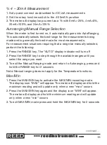
% 4 – 20mA Measurement 

1. Set up and connect as described for DC mA measurements

2. Set the rotary function switch to the 4-20mA% position
3. The meter will display loop current as a % with 0mA=-25%, 4mA=0%, 

20mA=100%, and 24mA=125%

Autoranging/Manual Range Selection

When the meter is first turned on, it automatically goes into AutoRanging. 

This automatically selects the best range for the measurements being 
made and is generally the best mode for most measurements.  
For measurement situations requiring that a range be manually selected, 
perform the following:

1. Press the RANGE key. The “AUTO” display indicator will turn off
2. Press the RANGE key to step through the available ranges until you 

select the range you want

3. To exit the Manual Ranging mode and return to Autoranging, press and 

hold the RANGE key for 2 seconds

Note: Manual ranging does not apply for the Temperature functions.

Max/Min

1. Press the MAX/MIN key to activate the MAX/MIN recording mode. 


The display icon “MAX” will appear. The meter will display and hold the 
maximum reading and will update only when a new “max” occurs

2. Press the MAX/MIN key again and the display icon “MIN” will appear. 

The meter will display and hold the minimum reading and will update 
only when a new “min” occurs

3. To exit MAX/MIN mode press and hold the MAX/MIN key for 2 seconds

continued ...

Summary of Contents for ST-9919

Page 1: ...reedinstruments www com Model ST 9919 TRMS Digital Multimeter Instruction Manual...

Page 2: ...Measurement 11 AC Current Measurement 12 Resistance Measurement 13 Continuity Check 13 Diode Test 13 Temperature Measurement 14 Capacitance Measurement 14 Frequency Measurement 14 4 20mA Measurement...

Page 3: ...ous voltages For maximum safety the meter and its test leads should not be handled when these terminals are energized Indicates that a instrument is protected throughout by double insulation or reinfo...

Page 4: ...per IEC 61010 2 USE EXTREME CAUTION when working with high voltages 3 DO NOT measure voltage if the voltage on the COM input jack exceeds 1000V ground 4 NEVER connect the meter leads across a voltage...

Page 5: ...IP67 dust and waterproof EN61010 1 Cat IV 600V Cat III 1000V Includes test leads and 9V battery Specifications Function Range Resolution Accuracy DC Voltage 400mV 0 01mV 0 06 reading 2 digits 4V 0 00...

Page 6: ...0M 0 001M 2 0 reading 10 digits Capacitance 40nF 0 001nF 3 5 reading 40 digits 400nF 0 01nF 4 F 0 0001 F 3 5 reading 10 digits 40 F 0 001 F 400 F 0 01 F 4000 F 0 1 F 5 reading 10 digits 40mF 0 001mF F...

Page 7: ...res peaks 1ms Temperature Sensor Requires type K thermocouple Input Impedance 10M VDC 3M VAC AC Response True RMS AC True RMS The term stands for Root Mean Square which represents the method of calcul...

Page 8: ...holster Size 7 36 x 3 2 x 2 0 187 x 81 x 50mm includes holster Safety This meter is intended for origin of installation use and protected against the users by double insulation per EN61010 1 and IEC6...

Page 9: ...6 amps cap m milli 10 3 volts amps A Amps k kilo 103 ohms F Farads capacitance M mega 106 ohms Ohms PEAK Peak Hold Hz Hertz frequency V Volts Percent duty ratio REL Relative AC Alternating current AUT...

Page 10: ...to the negative COM jack Insert the red test lead banana plug into the positive V jack 3 Touch the black test probe tip to the negative side of the circuit Touch the red test probe tip to the positive...

Page 11: ...nsert the black test lead banana plug into the negative COM jack 2 For current measurements up to 4000 A DC set the function switch to the yellow A position and insert the red test lead banana plug in...

Page 12: ...A mA jack 4 For current measurements up to 20A AC set the function switch to the yellow 10A HZ position and insert the red test lead banana plug into the 10A jack 5 Press the MODE button to indicate A...

Page 13: ...inuity on circuits or wires that have voltage on them 1 Set the function switch to the green CAP position 2 Insert the black lead banana plug into the negative COM jack Insert the red test lead banana...

Page 14: ...shock disconnect power to the unit under test and discharge all capacitors before taking any capacitance measurements Remove the batteries and unplug the line cords 1 Set the rotary function switch t...

Page 15: ...ng 1 Press the RANGE key The AUTO display indicator will turn off 2 Press the RANGE key to step through the available ranges until you select the range you want 3 To exit the Manual Ranging mode and r...

Page 16: ...s the REL button to exit the relative mode Display Backlight Press the HOLD key for 1 second to turn the backlight on The backlight will automatically turn off after 10 seconds Hold The hold function...

Page 17: ...r fuse covers WARNING To avoid electric shock do not operate your meter until the battery and fuse covers are in place and fastened securely This MultiMeter is designed to provide years of dependable...

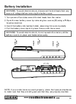
Page 18: ...er by removing two screws B using a Phillips head screwdriver 3 Insert the battery into battery holder observing the correct polarity 4 Put the battery cover back in place Secure with the screws WARNI...

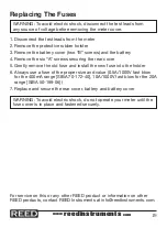
Page 19: ...cover 5 Gently remove the old fuse and install the new fuse into the holder 6 Always use a fuse of the proper size and value 0 5A 1000V fast blow for the 400mA range SIBA 70 172 40 10A 1000V fast blow...

Page 20: ..._______________ ________________________________________________ ________________________________________________ ________________________________________________ _____________________________________...

Reviews: