www.
reefe
.com.au
Ascento Group Australia
©
AI.062020
P: 1800 807 604
START UP (SINGLE DEVICE)
Be sure that the pump is correctly primed
Connect the device to the electric supply with the magnetothermic switch, FAILURE led light will be ON. Wait for 10 seconds while the device is doing
the autotest. Once it finishes, led light FAILURE is OFF and led light LINE is ON. The LCD screen will show message “SPEEDBOX ” and inmediately the
language display of the configuration mode.
The device is ready for being configured.
START UP (2 DEVICES ASSEMBLY)
If we wish to mount 2 devices for working in groups, previous point should be exactly followed - the order of connection is irrelevant. During the
configuration process we will be able to choose which device is the
MASTER
.
CONFIGURATION
.
Using
we can change the values and press
ENTER
for validation. Whenever we want to quit the configuration sequence press
MENU
. After every
ENTER
it will appears automatically the different screens that constitute the configuration sequence.
MENU
ENTER
ENTER
ENTER
ENTER
ENTER
ENTER
ENTER
ENTER
ENTER
P s e t
4 , 0
P b a r
3 , 9
P s e t
4 , 0
P b a r
3 , 9
L A N G U A G E
E N G L I S H
M A X . I N T
1 0
A
R O T A T I O N
0
M I N . F R E Q
1 5
H z
T Y P E
S I N G L E ?
P . S E N S O R
0 - 1 0
b a r
L E V E L ?
N O
OFF
START/
ON
P R E S S U R E
0 3 , 0
b a r
D I F
O N
0 , 5
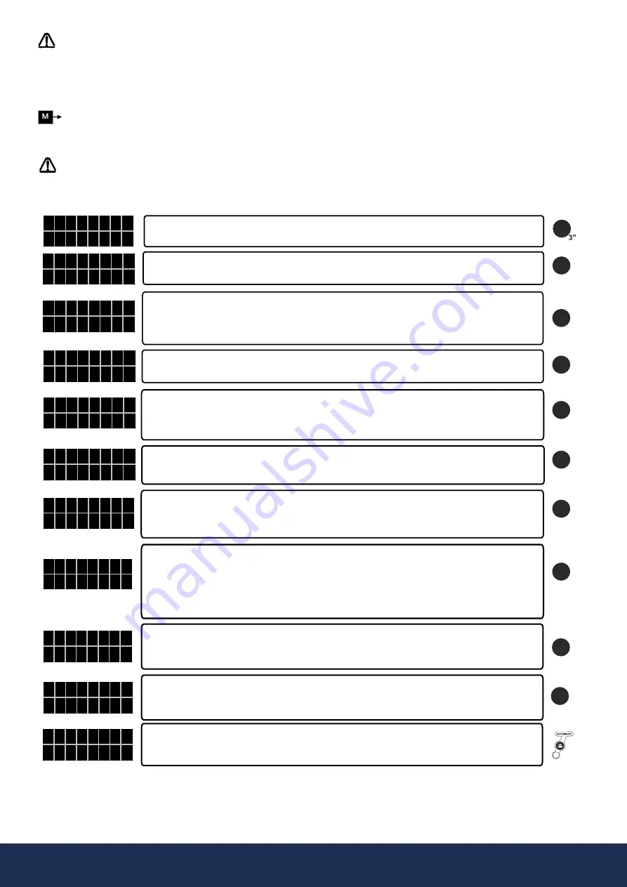
By mean of keys we can choose lanuages “LANGUAGE ENGLISH”,
“LANGUE FRANCAISE, ”LINQUA ITALIANA” AND IDIOMA ESPANOL”
To start the configuration sequence press
MENU
+
ENTER
during 3”
By mean of keys input the nominal current intensity value in A of the pump enabling the thermal
protection. This value is located over the characteristics plate of the motor. Press
ENTER
for validation.
WARNING: This value is linked with the flow detection system, it is very important to enter the exact
current consumption indicated on the name plate.
ROTATION SENSE.
Using the
START/STOP
pushbutton verify the rotation sense. By mean of keys (0/1)
we can change it. Press
ENTER
for validation.
MINIMUM FREQUENCY.
Using
we can increase the lower frequency value, within 15-48 Hz for 3-phase
pumps and 30-48 Hz for single-phase pumps.
*The minimum frequency value will be used as frequency stop in installations where the automatic detection of the device
do not act due to leaks in the system. See hydraulic installation.
EXTERNAL LEVEL SENSOR.
If the installation does not have level probe
press
ENTER
to validate NO.
If the installation has a level probe, use keys
to change NO by Y.
This will be the system operating pressure. Use keys
for modify the initial value (2 bar)
WARNING! The input pressure must be at least 1 bar lower than the maximum pressure of the pumps.
NOTE:
In case of group assembly, all system operates at the pressure set in the MASTER device, so that the
configuration of set pressure in the slave device is superfluous.
The default value is 0.5 bar. This value of pressure is substracted to the system setpoint, resulting the final
pressure to which the system will set in motion the pump when the hydraulic network has a demand. Use
keys pq to modify the initial value. It is recommended to maintain this value between 0.3 and 0.6 bar.
Example:
- Input pressure: 2 bar
- Differential start: 0.3 bar
- Final start pressure: 2-0.6 = 1.4 bar.
The device is configured by default as
SINGLE.
In case of individual assembly just confirm
SINGLE
by
pushing
ENTER.
In case of group assembly (M-S), we will choose respectively
SLAVE and MASTER
in each
unit pushing
.
The range of lecture of the pressure transmitter installed must be adjusted.
If the range is within 0-10 bar confirm by mean of
ENTER.
If the range is within 0-16 or 0-25 bar change it by mean of
and then confirm with
ENTER
After pressing
ENTER
pushbutton, the system is ready to operate. Press
AUTOMATIC
in order to quit manual
mode.
In case of group assembly press
AUTOMATIC
only in the device set as MASTER.
In case of group assembly, after pressing
AUTOMATIC
in the
MASTER
device, the
AUTOMATIC LED LIGHT
of the
SLAVE
device will start to flash
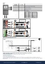
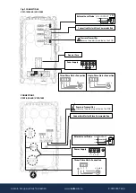
intermittently, indicating that communication between both devices is ready. If this does not happen verify the connection (Fig 5).


