42
l) Installing the servos (ARR version)
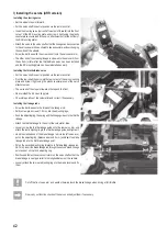
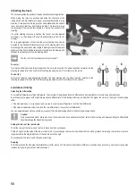
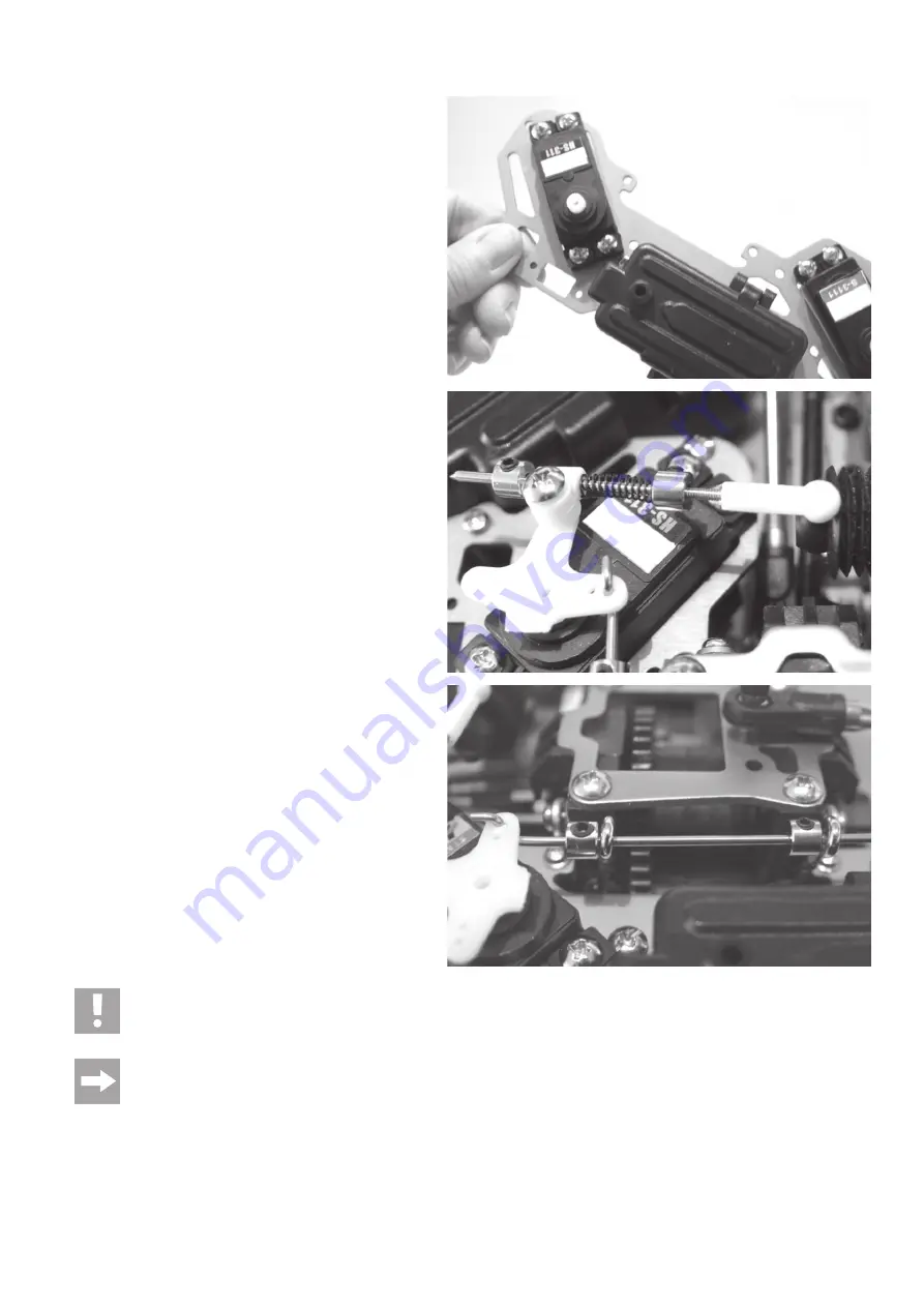
Installing the steering servo
• Set the wheels to point forward.
• Put the servo shaft in neutral position via the remote control.
• Insert the steering servo (servo shaft must point forward) into the front
cut-out of the RC mounting plate and screw it tight using the plastic
counter-pieces contained in the servo attachment set (at the bottom of
the RC mounting plate).
• Attach the servo to the servo shaft so that the linkage can be connected
to the servo saver arm in as straight a line as possible, without changing
the position of the wheels.
• Screw the ball head with the screw-on ball onto the servo saver arm.
• The other end of the steering linkage is screwed to the servo arm from
the bottom (or later after the throttle/brake servo has been installed
and the RC mounting plate has been reinstalled as well).
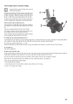
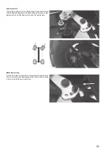
Installing the throttle/brake servo
• Put the servo shaft in neutral position via the remote control.
• From the top, insert the servo into the rear cut-out of the servo mounting
plate and screw it tight using the plastic counter-pieces of the servo
attachment set.
• The servo shaft has to point towards the top and the front.
• Now reinstall the RC mounting plate.
• Check idle position of the carburettor and correct it if necessary.
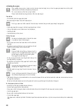
Installing the linkage rods
• Screw the ball head onto the thread of the linkage rod.
• Softly screw grub screws (1.5 mm) into the adjusting rings.
• Push the adjusting ring, the spring and the linkage guide onto the throttle
linkage.
• Attach the throttle linkage to the ball of the carburettor slide.
• Loosely screw the throttle linkage guide onto the rear servo arm and
attach the rear adjusting ring to the throttle linkage guide and tighten it.
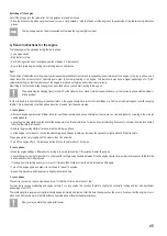
• Hook the cranked end of the brake linkage rod into the left servo arm,
put on the adjusting ring (distance approx. 9.5 mm) and insert the brake
linkage rod into the first brake linkage point.
• Put on the second adjusting ring (distance to first adjusting ring approx.
36.7 mm), insert the brake linkage rod through the second brake linkage
point and put on the third adjusting ring.
• Position and fasten the servo control arm on the servo shaft so that the
brake linkage is nearly parallel to the longitudinal axis of the vehicle.
• Loosely attach the two rear adjusting rings to the brake levers and fix
them.
Cut off the front servo arm as it would otherwise touch the brake linkage when driving at full throttle.
Now, carry out function checks of the servos and adjust them if necessary.
Summary of Contents for 23 68 22: RtR
Page 114: ...114 ...
Page 115: ...115 ...


