34
14. Light & Sound Function
a) General Information
The combiboard has eight LED outputs (“L1” to “L8”), and three digital inputs (“IN-1”, “IN-2”, “IN-3”) and an external RC
input (“PPM”) in addition to the composite signal converter.
Triggering of the LED outputs can be configured via 7 different modes.
The electronics either generate a fixed pattern on the outputs or the outputs are switched depending on the input
signals. The jumpers can be used to set modes, which can also be switched into three states by a RC signal (channels
5, 6, 7, 8 or external). Thus, it becomes possible to switch during flight.
Digital inputs:
The digital inputs switch the respective outputs when the respective mode was selected. A high signal (+5 V) means
that an output is switched on. The connected LED or the connected LED strip is lit.
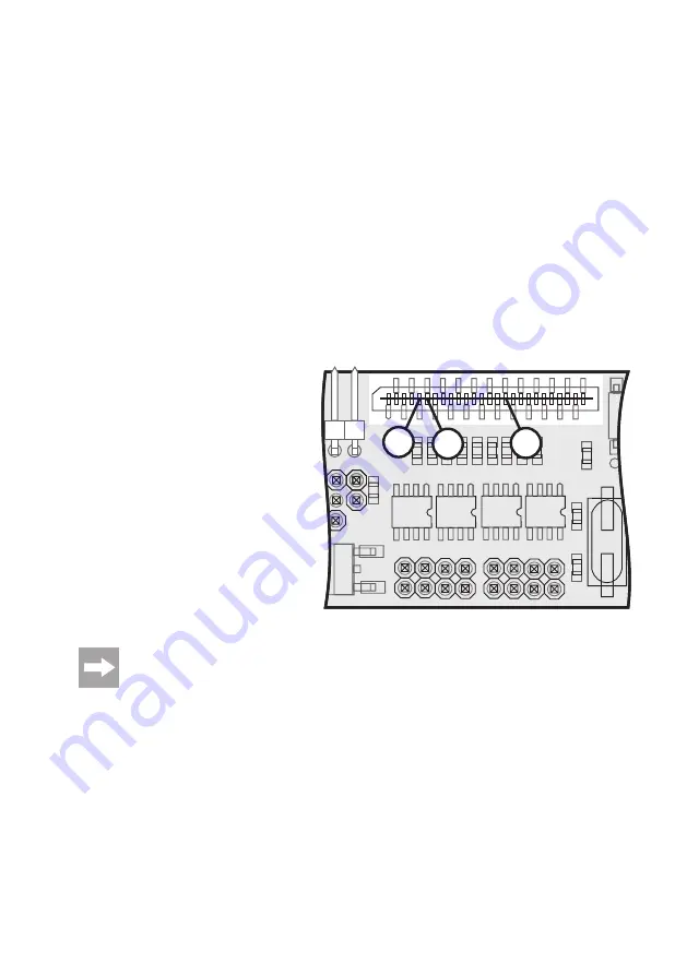
The three digital inputs are located at the interface connection “X10” and are assigned as follows:
IN-1 = contact 6
IN-2 = contact 5
IN-3 = contact 16
Different status displays or error messages of the QuadroCopter can be displayed well visibly via the 3
digital inputs. The function of the output signals mainly depends on the firmware used and can change
during further development of the QuadroCopter. A more detailed description with assignment of the 3
digital inputs can be taken from the text file of the respective firmware.
R2
T4
X9
IC2
T5
T2
T3
Q1
X4
X3
C3
C2
X10
C16
C1
1
C10
C9
C8
C13
C12
C15
C14
R23
R2
T4
T5
T2
T3
Q1
X10
C16
C1
1
C10
C9
C8
C13
C12
C15
C14
R23
IN-1
IN-3
IN-2
Figure 20
Summary of Contents for QuadCopter 650 ARF
Page 1: ... QuadroCopter 650 ARF Item no 20 93 00 Version 11 10 Operating Instructions ...
Page 24: ...24 i Possible Flight Modes Mode Throttle Yaw Pitch Roll 1 2 3 4 ...
Page 49: ...49 ...
Page 50: ...50 ...
Page 51: ...51 ...


