background image

23

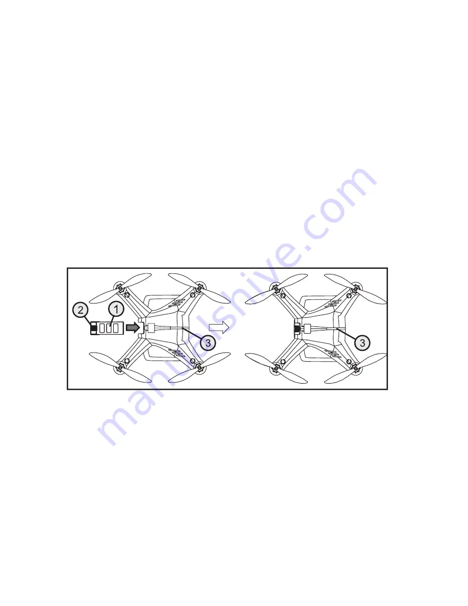
b) Inserting the Flight Battery into the Quadrocopter

To ensure a sufficiently good satellite reception, the quadrocopter should be set up on a free field, where no high-

voltage lines, power masts, metal constructions or other obstacles may impair GPS reception. 
Stay away from broadcasting systems and other facilities that may negatively influence the electromagnetic conditions 

in your environment. 
The flight field should also be free of obstacles such as buildings or trees to ensure unimpaired flight operation.
Choose a day with good whether and the least possible wind.
Before inserting the flight battery in the quadrocopter, check the voltage situation. For this, briefly push the on/off 

button (1) at the flight battery. All four LEDs must be lit for two seconds.
Switch on the remote control transmitter and check the correct function of the transmitter with the display. The trim-

ming displays (see figure 10, items 5, 6, 8 and 10) must be in the middle position. If this is not the case, the trimming 

must be set (see the following chapter 11. g).
Turn the rotating encoder „VRB“ to the centre position or check the centre position of the controller.
Now push the deactivated flight battery (see figure 16, item 1) into the quadrocopter with the charge connection con-

tacts first. Slightly push the grooved surface of the battery lock (see figure 16, item 2) so that the locking tab can latch 

and the flight battery is safely held in the quadrocopter. 
When the flight battery has been inserted into the quadrocopter and is locked properly, switch on the flight battery with 

the on/off button (see figure 6, item 1), so that the quadrocopter is supplied with power

Figure 16

The status LEDs (see figure 16, item 3) light up yellow (red and green) and the quadrocopter performs a self-test. After 

a brief time, the downward-pointing LEDs in the book arms will flash and the quadrocopter will emit a brief signal.
The gimbal swivels the camera holder into the home position and the status LEDs will briefly go out and then start to 

flash. The meaning of the flashing impulses is described in more detail below. 
When the binding between the transmitter and receiver is correct, the display of the remote control shows the voltage 

supply of the receiver (see figure 10, item 4). Push the buttons „UP“ or „DOWN“ at the transmitter to get more infor-

mation about the current reception of the GPS satellite. 

Summary of Contents for 1400004

Page 1: ...Operating Instructions Quadrocopter Shadow 2 0 RTF Item no 1400004 Version 10 16 ...

Page 2: ...the Flight Battery 14 e Testing the Rechargeable Battery Charge Condition 15 9 Transmitter Controls 16 10 Setting up the Transmitter 18 a Inserting the Batteries 18 b Switching on the Transmitter 18 c Setting the Control Stick Length 21 11 Commissioning of the Quadrocopter 22 a Checking Activation Deactivation function of the Flight Battery 22 b Inserting the Flight Battery into the Quadrocopter 2...

Page 3: ...1 Programming the Remote Control 44 22 The System Setting Menu System Setup 45 a Control stick Assignment Sticks mode 45 b Display Brightness LCD brightness 47 c Transmitter Software Version Firmware ver 48 d Transmitter Software Update Firmware update 49 e Reset to Factory Settings Factory reset 50 23 The Function Setting Menu Functions setup 51 a Control Encoder Test Display 52 b Basic Trim Subt...

Page 4: ...hird party Therefore retain these operating instructions for reference All company names and product names are trademarks of their respective owners All rights reserved If there are any technical questions please contact International www conrad com contact United Kingdom www conrad electronic co uk contact 2 Explanation of Symbols The symbol with a lightning bolt in a triangle is used where there...

Page 5: ...ct must not get damp or wet The product is not suitable for children under 14 years of age Observe all safety information in these operating instructions They contain important information on hand ling of the product You are solely responsible for the safe operation of your remote control and your model 4 Scope of Delivery Quadrocopter with 2D gimbal assembled ready to fly Radio remote control tra...

Page 6: ...2 to Mode 1 without any great effort and permits detailed control of the model Below the quadrocopter a camera holder 2D gimbal that is stabilised around two axes is installed It may hold action cams of the GoPro type or corresponding cameras with the same dimensions and permits a perfectly calm video in flight Legal note Observe the legal basics of your country regarding photographs and videos of...

Page 7: ...Note In some countries you are required to have insurance for all model aircraft The unauthorised conversion and or modification of the product is prohibited for safety and approval reasons This product is not a toy and not suitable for children under 14 years of age The product must not get damp or wet As delicate control electronics are used in the quadrocopter which are also sensitive to temper...

Page 8: ...e control system Watch out for any visible damage such as defective plug connections or damaged cables All moving parts on the model must run smoothly but must not have any tolerance in the bearing The flight battery required for operation must be charged before operation Ensure that the batteries in the transmitter have a sufficient remaining capacity transmitter indication If the batte ries are ...

Page 9: ...h off the flight battery before the remote control Then remove the flight battery from the quadrocopter Never switch off the remote control while the quadrocopter is still in operation Never expose your model and the remote control system to direct solar irradiation or great heat for an extended period ...

Page 10: ... model and the batteries There is a danger of fire and explosion Always replace the whole set of batteries Do not mix full batteries with half full ones Always use batteries rechar geable batteries of the same type and manufacturer Never mix batteries and rechargeable batteries Therefore only use batteries for the remote control transmitter If the device is not used for an extended period of time ...

Page 11: ...ed with the corresponding figure number a Assemblies Displays and Attachments Illustration A in figure 1 shows the quadrocopter from the front Illustration B in figure 1 shows the quadrocopter from the rear Figure 1 1 Propeller 2 Propeller nut 3 Status LEDs 4 Propeller arm lighting front 5 Landing frame 6 2D gimbal 7 Brushless motor 8 USB interface 9 Propeller arm lighting rear 10 Battery box with...

Page 12: ...e glued in attachment nuts see figure 2 item 3 which tighten when the quadrocopter is in operation To attach the propellers place the respective propellers on the threads of the motor shafts and manually turn the propellers contrary to the regular operating rotating direction Hold the bell of the brushless motor with the other hand Wear protective gloves when installing the propellers to avoid inj...

Page 13: ...gimbal when transporting the quadrocopter The covers must be removed before in serting the flight battery or the camera Otherwise the gimbal cannot perform the required movements and is thus destroyed Never operate the camera holder without a camera inserted The missing weight of the camera will cause the holder to be unbalanced which will put too much of a strain on the controlling electronics wh...

Page 14: ...ated in LED 3 and LED 4 as charging continues Before charging is complete all 4 LEDs will be permanently lit When the flight battery is fully charged the four LEDs at the flight battery 7 will go out and the control indicator at the mains unit 6 will light up green Once charging is completed disconnect the flight battery from the charge adapter and pull the mains plug from the mains so cket The co...

Page 15: ...charge condition When the flight battery is discharged only LED 1 will be lit if it is fully charged all four LEDs will be lit At a partially discharged flight battery e g LED 1 and LED 2 would be permanently lit and LED 3 may flash The display of the rechargeable battery voltage above the four LEDs only serves as a general indication The precise battery voltage can be read in operation of the qua...

Page 16: ...16 9 Transmitter Controls Figure 7 ...

Page 17: ...for roll function 8 OK button 9 Button CANCEL 10 On off switch 11 LC display 12 BIND AUTO FOLLOW button 13 DOWN button 14 UP button 15 Trim button for yaw function 16 Control stick for the yaw and pitch functions 17 Trim button for pitch function 18 Toggle switch IOC 19 Toggle switch GO HOME 20 Eyelet for shoulder belt 21 Rotary encoder VRA Rear figure 8 22 GPS receiver connection socket 23 Batter...

Page 18: ... battery compartment back on from the bottom until the locking mechanism engages b Switching on the Transmitter After you have inserted four new batteries check the position at the toggle switches All switches must be in the front top position The two control sticks are held in the middle position by spring power Now switch on the transmitter using the on off switch see fig 7 item 10 First three s...

Page 19: ...de 10 Pitch trimming display 11 Display for GPS reception of the transmitter The display only appears when the GPS receiver has been connected to the transmitter If one of the three toggle switches see figure 7 item 4 18 and 19 is not in the front position warning sounds will be emitted when activating and the corresponding note is displayed see figure 11 In this case the affected switches must be...

Page 20: ... Flight mode GPS Mode Example in figure 12 The two upper figures show the displays without GPS reception of the quadrocopter The two lower ones represent a display with GPS reception If the power supply is not sufficient for correct transmitter operation anymore the battery icon will flash at a voltage of less than 4 2 V and the transmitter emits acoustic warning sounds at regular intervals The mo...

Page 21: ...ticks depending on your steering habits To do so simply hold the bottom part of the grip 1 and turn the upper part 2 up anti clockwise You can now set the length of the control stick by turning the bottom part of the grip Finally tighten the upper part of the grip back up Figure 13 ...

Page 22: ...utton 1 at the flight battery and release it again at once When the flight battery is fully charged the four LEDs of the flight battery will start to light up Now push the on off button 1 again and keep it pushed The four LEDs will go out and start to light up again in sequence LED 1 to LED 4 When all four LEDs are lit release the button again The flight battery is now on and voltage is pending on...

Page 23: ...entre position or check the centre position of the controller Now push the deactivated flight battery see figure 16 item 1 into the quadrocopter with the charge connection con tacts first Slightly push the grooved surface of the battery lock see figure 16 item 2 so that the locking tab can latch and the flight battery is safely held in the quadrocopter When the flight battery has been inserted int...

Page 24: ... position position 2 and back The status LEDs at the quadrocopter must be permanently lit yellow red and green Hold the quadrocopter horizontally see figure 17 illustration A and turn it around its vertical axis until the status LEDs switch to green at least 360 Then hold the quadrocopter with the front propellers vertically down and turn it 360 around the longitudinal axis see figure 17 illustrat...

Page 25: ... With the pitch function you can control the flight altitude of the quadrocopter see figure 18 The left control stick also see figure 7 item 16 is used for control In contrast to other remote control systems where the control stick for the pitch function can be moved forward and back without springing back to the middle position the pitch control stick has a middle position in the quadrocopter Sha...

Page 26: ...ncrease the speed of the propeller turning to the right clockwise and at the same time rescue there speed of the propellers turning to the left counter clockwise This way the entire lift force remains the same but only one torque acts on the model which turns the quadrocopter around its vertical axis to the left see figure 19 If the control stick is moved to the right the speed changes of the prop...

Page 27: ...also see figure 7 item 6 If the stick is slightly moved to the left the electronics in the quadrocopter change the propeller speeds so that the model will turn to the left slightly and thus also fly to the left If you move the transmitter to the right the speed changes of the propellers are precisely inverted and the model will fly sideways to the right Figure 20 ...

Page 28: ...ck also see figure 7 item 6 If the stick is slightly pushed to the front the electronics in the quadrocopter change the propeller speeds so that the model will turn to the front slightly and thus also fly forward If you move the transmitter to the rear the speed changes of the propellers are precisely inverted and the model will fly to the rear Figure 21 ...

Page 29: ...quadrocopter is to be used indoors e g in a hall or apart ment etc the switch GPS must be put in the bottom position GPS off Since operation indoors does not have GPS support beginners and inexperienced model pilots should initially only operate the quadrocopter outdoors and with GPS support For more information on this see the following chapter 12 The switches have the following functions Switch ...

Page 30: ...tant Do not deflect the control stick for the pitch function too much otherwise the quadrocopter will rise very quickly or drop too quickly Never try grabbing the flying quadrocopter with your hand There is a considerable danger of injury Perform the first careful direction controls at an altitude of 1 2 m and observe how the quadrocopter reacts to the control commands To land the quadrocopter aga...

Page 31: ...e figure 7 item 7 to the left until the quadrocopter stops trying to drift to the right The remote control emits a short signal sound for each press of a trim stick The tone height depends on the trimming direction The middle position is acoustically indicated by a longer signal The set value is automatically saved and is retained even after switching the transmitter off and on The other three con...

Page 32: ...satellites received No red flashing impulses 7 or less GPS satellites are received The LED display flashes only green every 5 se conds The more satellites are received the more precise will the automatic positioning of the quadrocopter in flight be The quadrocopter has a fixed warning threshold that protects the flight battery from deep discharge If the voltage of the flight battery drops below th...

Page 33: ...atically maintain the last position altitude when the control sticks at the transmitter are in their middle positions In GPS mode the IOC function Intelligent Orientation Control can be activated c IOC Function Smart Flight Orientation Without IOC function Intelligent Orientation Control the movement directions always refer to the build of the quadrocopter The side with the status LEDs is front Lo...

Page 34: ...oint Of Interest Attention When the quadrocopter is in IOC Mode and flies farther away do not push the IOC switch repeatedly since this will overwrite saved values and e g the return home point will be in an entirely different location also see chapter 13 d CL Mode In CL Mode Course Lock the quadrocopter uses its installed compass to measure its alignment When the quadrocopter has been aligned e g...

Page 35: ...t least 5 m from the starting point in which the HL mode cannot be activated or that the quadrocopter maintains automatically when flying Figure 27 f POI Mode In POI Mode Point Of Interest the movement direction of the quadrocopter refers to a freely selectable point in the terrain with which the quadrocopter is aligned with its front By steering to the right and left you can choose the direction ...

Page 36: ...t or the point of interest This is partially done automatically or can be performed manually CL Mode The mode is only available if the switch IOC has been reprogrammed to the combination A or B The alignment of the quadrocopter is automatically recognised 36 seconds after plugging in of the flight battery More than 6 GPS satellites must be received To manually save the alignment the switch IOC mus...

Page 37: ...uickly 20 x 14 Go Home Function The quadrocopter has a Go Home function that returns the quadrocopter to the starting point automatically or by remote control command The prerequisite for this function is that the starting point has been saved see HL Mode and that the quadrocopter is flying in GPS Mode and receives more than 6 GPS satellites The distance between the quadrocopter and the saved star...

Page 38: ...he product you can set if the quadrocopter is to perform the go home function or hover in place when it loses contact Important When the quadrocopter receives fewer than 6 satellites or is not in GPS Mode the Go Home function is no longer available If the quadrocopter is in a difficult to control situation or very far away from the pilot s site activate the return function with the Go Home switch ...

Page 39: ... take the quadrocopter into operation calibrate the com pass and then switch it to GPS Mode Start the quadrocopter and fly it to the desired position in which it is to follow the remote control transmitter When the quadrocopter is in the desired position push the but ton BIND AUTO FOLLOW 3 The quadrocopter will now align with the transmitter and follow any movement of the transmitter in the same a...

Page 40: ...switching the quadrocopter off Even if the flight direction can still be controlled within limits during independent landing we recommend not to fly this long Observe the voltage display at the flight battery and the transmitter and land in time 17 Failsafe Function The failsafe function protects the quadrocopter from crashing when it receives no valid remote control signal anymore In the assistan...

Page 41: ...rts military systems and other protection worthy facilities The quadrocopter has a digital map in which these zones are shown In connection with its intelligent orientation function the quadrocopter can tell when it enters a flight prohibition zone if in GPS Mmode In this case the status LEDs will flash red 10 x If the flight prohibition zone has been entered the quadrocopter will no longer react ...

Page 42: ...amera can be swivelled from the horizontal position vertically up by 45 and down by 135 The swivel movement is controlled with the rotary controller VRB 1 Figure 32 Caution important Never operate the camera holder without a camera inserted The missing weight of the camera will cause the holder to be unbalanced which will put too much of a strain on the controlling electronics which may be damaged...

Page 43: ...mity distance approx 50 cm Switch off the transmitter Disconnect the two plug connectors 1 with which the quadro copter is connected to the receiver from the receiver Connect the enclosed programming plug 2 to the B VCC connection of the receiver with the cable loop The receiver must be supplied with power via a receiver bat tery that is connected to any output of the receiver 3 Ensure correct pol...

Page 44: ...the batteries The functions of the operating elements OK button To call the programming menus briefly push the button OK with the transmitter on The displayed operating display switches to the menu display and the transmitter switches to programming mode This button can also activate selec ted settings If the button is pushed or longer the factory settings stored in the menu item are called CANCEL...

Page 45: ...for you in the system setting menu Function Display Control stick assignment Sticks mode Display brightness LCD brightness Transmitter software version Firmware ver Transmitter software update Firmware update Factory reset Factory reset a Control Stick Assignment Sticks mode As already described in chapter Commissioning of the Quadrocopter the two control sticks are assigned specific control funct...

Page 46: ...ding to the control stick assignment Pushing the buttons UP or DOWN permits setting the desi red control stick assignment Mode 1 to Mode 4 Keep the button CANCEL pushed for a longer period to save the settings The display then shows the system setup menu again Push the button CANCEL repeatedly until you get back to the operating display Note Any change to the control stick assignment is only possi...

Page 47: ...ntly set brightness value is displayed with a nume ric value and a bar chart in the display To better assess the brightness settings the quadrocopter is displayed as a model icon at the lower display edge of the display as well Push the buttons UP or DOWN to select the desired display brightness now If the button OK is pushed and held the fac tory parameters are called Keep the button CANCEL pushe...

Page 48: ...ollowing menu item Display of the Transmitter Software Version Switch on the transmitter and call the system setting menu Move the cursor arrow to the menu item Firmware ver with the two buttons UP and DOWN Briefly push the button OK to activate the menu item The transmitter designation software version and date of the transmitter software are displayed in the display Push the button CANCEL repeat...

Page 49: ...e transmitter is switched to the update mode and all functions are stopped You are as ked to push the button OK to activate the update function After pushing the button OK a safety prompt appears Pushing the buttons UP or DOWN switches the cursor ar row from No to Yes Push the button OK again to activate the update function The push of the button is in this case not confirmed with a sound but the ...

Page 50: ...utely necessary Factory reset Switch on the transmitter and call the system setting menu Move the cursor arrow to the menu item Factory reset with the two buttons UP and DOWN Briefly push the button OK to activate the menu item The display shows the message that the transmitter deletes all entered settings when resetting to factory settings You are asked to push the button OK to activate the reset...

Page 51: ... to the menu display The selection window around the remote control icon shows that you can call the sys tem setup menu in this setting Push the button UP or DOWN so that the selection window frames the tools Briefly push the button OK to get to the function settings menu The two menu items of the function setup menu are now dis played The following setting functions are available for you in the f...

Page 52: ...channels in the current position of the encoders If you move the control sticks or switches in different direc tions now you will see precisely which channel is controlled in which direction By pushing the buttons UP and DOWN you can switch the display to channels 7 10 and test the dial switches VRA and VRB there Push the button CANCEL repeatedly until you get back to the operating display Since t...

Page 53: ...ally Setting the Basic Trim Switch on the transmitter and call the function setting menu Move the cursor arrow to the menu item Subtrim with the two buttons UP and DOWN Briefly push the button OK to activate the menu item In the display you will see display items for the six control func tions with the respective currently set trim values Push the buttons UP or DOWN to select the base trim for cha...

Page 54: ...s service life dispose of the product according to the relevant statutory regulations Remove any inserted batteries or rechargeable batteries and dispose of them separately from the product b Batteries and Rechargeable Batteries You as the end user are required by law Battery Ordinance to return all used batteries rechargeable batteries Dis posing of them in household waste is prohibited Batteries...

Page 55: ...era holder Motors cannot be started with the flight battery fully charged Control sticks are mechanically blocked and will not reach the end position in the respective inner lower corner Middle position of the trim is misadjusted too far Following function does not work Check the power supply of the quadrocopter and the remote cont rol The quadrocopter does not receive at least 7 or more GPS satel...

Page 56: ...copter does not receive at least 7 or more GPS satel lites 27 Declaration of Conformity DOC The manufacturer hereby declares that this product complies with the essential requirements and regulations and all other relevant provisions of the 1999 5 EC directive The compliance statement for this product is available at www conrad com 28 Technical Data Transmitter Frequency range 2 4 GHz Number of ch...

Page 57: ...ble battery Max turning angle 200 s Max tipping angle 35 Max rising speed 6 m s Max dropping speed 2 m s Max flight speed 15 m s in Smart GPS mode only LiPo rechargeable battery Voltage 11 1 V Capacity 6400 mAh 10C Max charge current 6 A Max discharge current 64 A Permanent discharge current 32 A Dimensions 55 x 45 x 145 mm Weight 460 g Mains unit Input voltage 110 240 V AC 50 60 Hz Output voltage...

Page 58: ...58 ...

Page 59: ...59 ...

Page 60: ...n reserved Reproduction by any method e g photocopy microfilming or the capture in electronic data processing systems require the prior written approval by the editor Reprinting also in part is prohibited This publication represent the technical status at the time of printing Copyright 2016 by Conrad Electronic SE 1400004_V3_1016_01_VTP_m_en ...

Reviews: