58
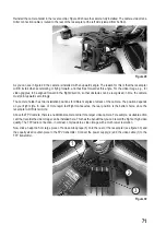
Place the racecopter on a level, free surface when installing the propellers. The arrow in figure 8 marks the flight
direction of the racecopter = front.
Remove the propeller nuts from the motors. For this, you need a round mandrel (e.g. a small screwdriver with a shaft
diameter of approx. 1.5 to 2 mm).
The threads of the propeller tappets are different (left-hand thread or right-hand thread). This is so that the
nuts cannot come free on their own in operation (when the propeller turns).
• Left-hand turning propeller = right-hand thread -> turn the nut to the left for loosening
• Right -hand turning propeller = left-hand thread -> turn the nut to the right for loosening
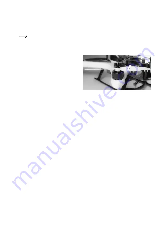
You can recognise the running direction of the propeller
by the raised surface of the propeller pointing in the
running direction.
Figure 9 shows a propeller with the running direction
"left" (counter-clockwise viewed from the top).
Place the white and black propellers onto the motors according to the alignment in figure 8 (the arrow marks the flight
direction of the racecopter = front). Pushing them on may take a little strength, but do not apply force and do not use
a tool for pushing them on.
Then put the nuts onto the propeller tappets again and tighten them only hand-tightly. Observe as described above
that the nuts must fit the threads (nuts/propeller tappets with left-/right-hand thread). Do not use any force when
tightening the nuts.
c) Inspection of the Drive
Before taking your racecopter into operation, you need to check the drive.
It is important that all propeller nuts are properly tightened and that the propellers will turn easily. For this, turn every
single propeller with your finger carefully and check concentricity and smooth operation. Only the magnetic force of
the motors must be clearly noticeable here.
Observe the rotating directions of the different propellers. Two propellers turn clockwise and two propellers turn
counter-clockwise (see chapter 10. b).
Figure 9


