37
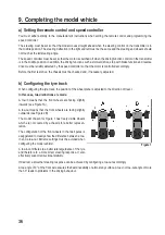
Before adjusting the tie rod, check the position of the
steering or the steering linkage (see Figure 19 in the as-
sembly instructions).
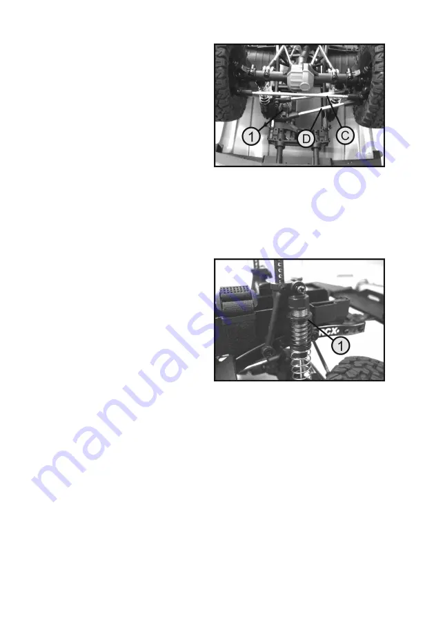
If the servo lever (see Figure 2, no. 1) is facing forward in
the direction of travel, both wheels should be oriented so
that the model moves straight forward.
If the wheels have a slight left or right steering deflection,
first adjust the steering linkage (see Figure 19, no. D in the
assembly instructions). If necessary, remove the steering
linkage from the servo or the steering knuckle and adjust it
to the required length by turning the ball joints.
The toe-in/out on the front axle can be adjusted by chang
-
ing the length of the tie rod (see Figure 19, no. C in the
assembly instructions).
If necessary, the ball joints should also be unscrewed. The tie rod can be adjusted to the required length by turning
the ball joints.
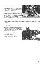
c) Adjusting the shock absorbers
The stiffness of the shock absorbers can be adjusted sep-
arately using a dial (1). If you screw the dial further down,
the springs will generate a higher preload and the shock
absorbing properties will become stiffer.
If you screw the dial further up, the preload of the shock
absorber spring will be reduced and the shock absorbing
properties will become softer.
For the first drives on rough terrain, we recommend that
you adjust the shock absorbers a bit softer.
Figure 2
Figure 3

