background image

4

1. Introduction

Dear customer,
Thank you for purchasing this product.
This product complies with the statutory national and European requirements.
To maintain this status and to ensure safe operation, you as the user must observe these operating instructions!

  These operating instructions are part of this product. They contain important notes on commissioning and 

handling. Also consider this if you pass on the product to any third party. Therefore, retain these operating 

instructions for reference!

If there are any technical questions, please contact:  www.conrad.com/contact

2. Explanation of symbols

  The symbol with the exclamation mark in the triangle is used to indicate important information in these 

operating instructions. Always read this information carefully.

  The arrow symbol indicates special information and advice on operation. 

3. Intended use

The transmitter has 4-channels and operates on a 2.4 GHz automatic frequency hopping digital system (AFHDS). It 

comes with a compact receiver that has an integrated antenna. The receiver uses standard PWM output. Extra chan-

nels are available for various switching tasks or control functions.
Contact with moisture must be avoided under all circumstances.
For safety and approval purposes, you must not rebuild and/or modify this product. If you use the product for purposes 

other than those described above, the product may be damaged. In addition, improper use can result in other hazards. 

Read the instructions carefully and store them in a safe place. Make this product available to third parties only together 

with its operating instructions.
All company names and product names are trademarks of their respective owners. All rights reserved.

4. Delivery content

•  Transmitter 
•  Receiver antenna

•  Hint sheet
•  Operating instructions (on CD-ROM)

Summary of Contents for 2267650

Page 1: ...Operating Instructions 4 Channels Gen4 Pistol Grip Remote Control 2 4 GHz Item No 2267650 Page 2 18 ...

Page 2: ... Operating elements 8 a Transmitter 8 b Receiver antenna 10 8 Transmitter batteries 10 9 Standard wiring diagrams 11 a Electronic speed controller E S C 11 b Gas powered motors 11 10 Operation 12 a Power ON 12 b Binding transmitter with receiver 12 c Calibrate steering and throttle 12 d Power OFF 13 11 Controls 13 a Transmitter channels 13 b Beginner mode 14 c Channel reverse 14 d Fail safe safety...

Page 3: ...3 12 Care and cleaning 17 13 Declaration of Conformity DOC 17 14 Disposal 17 a Product 17 b Rechargeable batteries 17 15 Technical data 18 a Transmitter TX 18 b Receiver RX antenna 18 ...

Page 4: ...tes special information and advice on operation 3 Intended use The transmitter has 4 channels and operates on a 2 4 GHz automatic frequency hopping digital system AFHDS It comes with a compact receiver that has an integrated antenna The receiver uses standard PWM output Extra chan nels are available for various switching tasks or control functions Contact with moisture must be avoided under all ci...

Page 5: ...where interference from other radio controlled activity may occur Near power lines or communication broadcasting antennas Near people or roads On any body of water when passenger boats are present Do not use the product at night or in bad weather such as rain or thunderstorms Before use Set the Fail safe See d Fail safe safety mechanism on page 14 Turn the transmitter ON first and then turn the re...

Page 6: ...or an authorised repair centre If you have questions which remain unanswered by these operating instructions contact our technical support service or other technical personnel b Operation Make sure you are sufficiently insured for the operation of the model e g by a personal liability insurer If you already have personal liability insurance check with your insurance company if the operation of the...

Page 7: ...and model are both vertical e Rechargeable batteries Correct polarity must be observed while inserting the rechargeable batteries The rechargeable batteries should be removed from the device if it is not used for a long period of time to avoid damage through leaking Leaking or damaged rechargeable batteries might cause acid burns when in contact with skin therefore use suitable protective gloves t...

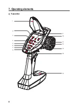
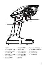
Page 8: ...8 7 Operating elements a Transmitter 2 1 3 4 5 8 6 9 11 13 15 14 7 12 10 ...

Page 9: ...een G LED 6 Throttle trim TH TRIM 7 Steering D R ST D R 8 Power switch ON OFF 9 Bind button BIND 10 Throttle reverse TH REV 11 Steering trim ST TRIM 12 Throttle trim TH TRIM 13 Steering D R ST D R 14 Lanyard eye 15 Base battery compartment 16 Three position AUX switch CH3 17 AUX button CH4 18 Steering wheel CH1 19 Throttle lever CH2 ...

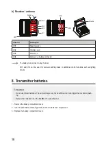
Page 10: ...or various switching tasks or additional control functions such as lighting circuits 8 Transmitter batteries Important Do not use lithium batteries The output voltage may not be sufficient and can trigger the low battery warn ing Replace the batteries when the G LED on the panel flashes 1 Remove the battery compartment cover 2 Insert 4x AA batteries matching polarity as shown inside the compartmen...

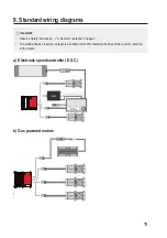
Page 11: ...nt Observe Safety instructions c Receiver antenna on page 7 Two sided adhesive foam servo tape is a suitable method for fastening the base of the receiver antenna to the model a Electronic speed controller E S C E S C b Gas powered motors ...

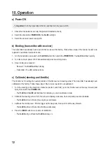
Page 12: ...mitter The LED will be solid on c Calibrate steering and throttle This function is for setting the neutral position of throttle lever and steering wheel The transmitter has already been calibrated at the factory Follow these steps if the receiver needs to be recalibrated 1 Turn the steering to the maximum clockwise position and hold push the throttle lever all the way forward and hold then switch ...

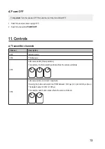
Page 13: ...er channels Channel Description CH1 Steering servo CH2 Throttle servo CH3 AUX servo switch three positions For example the three switch positions affect the servos as follows v CH4 AUX servo button minimum maximum Pressing the button will switch the PWM between 1000 µs min and 2000 µs max The default output of CH4 is 1000 µs For example each button press affects the servo as follows ...

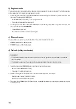
Page 14: ...These switches are used to reverse the direction of movement in relation to the input ST REV Reverses CH1 steering input TH REV Reverses CH2 throttle input d Fail safe safety mechanism Important The fail safe determines what the receiver will do if it loses the signal from the transmitter and includes the servo position If no fail safe has been set the receiver will not output any signals when the...

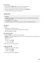
Page 15: ...djustment range is 120 µs to 120 µs each step is 4 µs max 30 adjustments each way 1LED indicator The G LED Lights up each time an adjustment is made Will not light when the maximum number of adjustments has been reached Will blink at the default zero setting 2Steering trim ST TRIM By default ST TRIM is set to adjust the trim for CH1 steering ST TRIM can be reassigned to adjust the trim for CH3 or ...

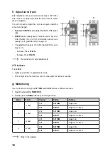
Page 16: ... Press ST D R Increase Press ST D R Press and hold for rapid adjustments 1LED indicator The G LED Lights up each time an adjustment is made Will not light when the maximum number of adjustments has been reached g Multiplexing Use this function to assign the ST TRIM and ST D R buttons to different channels 1 Switch the transmitter POWER ON 2 Double press the BIND button to cycle through modes Mode ...

Page 17: ...ic devices are recyclable waste and must not be disposed of in the household waste At the end of its service life dispose of the product in accordance with applicable regulatory guidelines Remove any inserted rechargeable batteries and dispose of them separately from the product b Rechargeable batteries You as the end user are required by law Battery Ordinance to return all used rechargeable batte...

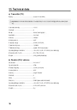
Page 18: ... Transmission power 20 dBm Transmission range approx 300 m open area Operating Storage conditions 10 to 60 C 20 95 RH non condensing Dimensions W x H x D 97 x 193 x 160 mm Weight 250 g without batteries b Receiver RX antenna Input power 3 5 to 8 4 V Ingress protection IPX4 Wireless frequency 2 406 2 474 GHz Wireles protocol ANT Antenna single internal Channels 4 RSSI no Data port PWM pulse width m...

Page 19: ...rved Reproduction by any method e g photocopy microfilming or the capture in electronic data processing systems require the prior written approval by the editor Reprinting also in part is prohibited This publication represent the technical status at the time of printing Copyright 2020 by Conrad Electronic SE 2267650_v2_1220_02_dh_m_en ...

Reviews: