background image

46

b) Checking the control functions

Before checking the control functions of the model, make sure that the rotating and suction area of   the propellers is 

free from loose objects, body parts or hair. Have an assistant hold the model firmly so that it cannot roll away during 

the motor check. The thrust produced by the running propeller can very easily blow small and light objects, such as 

spare propellers, off the table. 
Slowly push the joystick for the drive motors forward. The motors must start and speed up or slow down depending 

on the position of the joystick.

When the right joystick is deflected to the left, the right motor must speed up and the left motor audibly slow down (see 

also Figure 11). When the right joystick is pushed to the right, the motors must behave the other way around (see also 

Figure 12). Much noise is produced when changing speeds.

  The direction control can also be checked when the joystick for the drive motors is in the lowest position 

(motor off).

c) Checking the Gyro function

The model is equipped with a position sensor that detects whether a change in direction has been transmitter con-

trolled or not. When deflection of the model occurs e.g. due to a gust of wind, the stabilisation system (Gyro) detects 

the uncontrolled deflection of the model and automatically counteracts it. 

To check the function of the stabilisation system, hold the model with your hand from below and let the motors run at 

approx. 30 - 50% power. The direction control joystick must be in the middle position and must not be manipulated 

during the Gyro test.
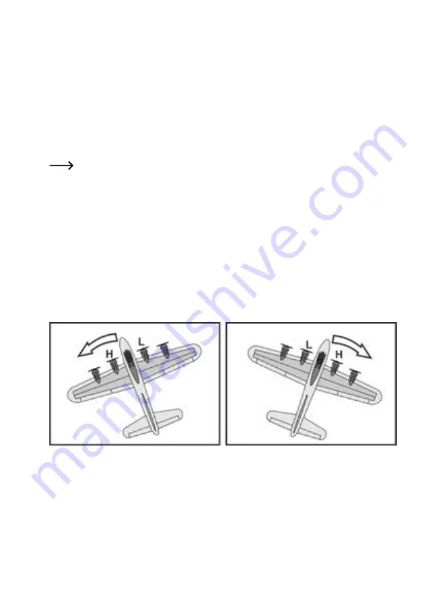
When turning the model around the vertical axis to the left at this point, the left propeller must speed up (H) and the 

right propeller slow down (L). When turning the model to the right, the right propeller must speed up (H) and the left 

propeller slow down (L) (see Figure 14). Even now the changing motor speeds can be heard very clearly.

Figure 14


Summary of Contents for 2373336

Page 1: ...Bedienungsanleitung Elektro Flugmodell Fortress Gyro RtF Best Nr 2373336 Seite 2 28 Operating Instructions Electric model aircraft Fortress Gyro RtF Item no 2373336 Page 29 54...

Page 2: ...e des Seitenleitwerkes 13 b Montage des Fahrwerks 13 c Einsetzen und Anschlie en des Flugakkus 14 10 Bedienelemente des Senders 15 11 Inbetriebnahme des Senders 15 a Einlegen der Batterien 15 b Einsch...

Page 3: ...n Sie deshalb diese Bedienungsanleitung zum Nachlesen auf Alle enthaltenen Firmennamen und Produktbezeichnungen sind Warenzeichen der jeweiligen Inhaber Alle Rechte vorbehalten Bei technischen Fragen...

Page 4: ...gefahrlosen Betrieb des Modells verantwortlich 4 Produktbeschreibung Bei dem Elektro Flugmodell Fortress handelt es sich um ein bereits weit vorgefertigtes RtF Modell Ready to Fly Der Rumpf die Tragfl...

Page 5: ...eferten Modells k nnen erheblich von dem in der Anleitung gezeigten Muster abweichen Bild 1 1 Flugmodell 2 Seitenleitwerk 3 USB Ladekabel 4 LiPo Flugakku 5 Zwei Ersatzpropeller 6 Fernsteuerung 7 Haupt...

Page 6: ...besteht eine Versicherungspflicht f r alle Flugmodelle Informieren Sie sich auch ber die lokalen gesetzlichen Vorschriften zum Betrieb von Flugmodellen In Deutschland sind zum Beispiel die Regelungen...

Page 7: ...Sie vor jeder Inbetriebnahme den korrekten und festen Sitz der Propeller Achten Sie bei laufenden Propellern darauf dass sich weder Gegenst nde noch K rperteile im Dreh und Ansaugbereich der Propelle...

Page 8: ...worfen werden Es besteht Explosionsgefahr Ausgelaufene oder besch digte Batterien Akkus k nnen bei Ber hrung mit der Haut Ver tzungen verur sachen benutzen Sie deshalb in diesem Fall geeignete Schutzh...

Page 9: ...Akku verformt bzw aufgebl ht sein darf er auf keinen Fall aufgeladen werden In diesem Fall besteht akute Brand und Explosionsgefahr Besch digen Sie niemals die Au enh lle des Flugakkus zerschneiden Si...

Page 10: ...e Temperatur als 60 C haben ggf zus tzliche Herstellerangaben auf dem Akku beachten F r den Transport von LiPo Akkus gibt es spezielle Transporttaschen die die Folgen eines pl tzlichen Brandes oder ei...

Page 11: ...ann Der Dauerstrom sollte nicht h her sein als die H lfte des angegebenen Wertes Achten Sie darauf dass die einzelnen Zellen eines Lithium Akkus nicht tiefentladen werden Eine Tief entladung eines Lit...

Page 12: ...eil an z B ein USB Port in einer Tastatur o da hier der Strom f r die Ladefunktion nicht ausreicht Das Betriebssystem eines Computers erkennt beim An schluss des Ladekabels keine neue Hardware da der...

Page 13: ...bunden hat k nnen Sie das Seitenleitwerk exakt ausrichten Das Seitenleitwerk muss im 90 Winkel zum H henleit werk 3 ausgerichtet werden Bei korrekter Montage sind die beiden Strecken A1 und A2 gleich...

Page 14: ...haltet befinden Schlie en Sie den Flugakku am verpolungssicheren Ste cker der Modellelektronik 5 an Versuchen Sie den Akku soweit wie m glich vorne im Schacht zu platzieren Nutzen Sie bei Bedarf ein k...

Page 15: ...gen Sie 3 Batte rien vom Typ Mignon AA Verwenden Sie ausschlie lich Batterien 1 5 V Zelle und keine Akkus 1 2 V Zelle f r die Stromversorgung des Senders Zum Einlegen der Batterien gehen Sie wie folgt...

Page 16: ...t tigen beginnt die LED des Sendes 2 zu blinken Schieben Sie nun den Steuerkn ppel f r die Antriebsmo toren ganz nach vorne oben und wieder zur ck in die hintere untere Position Die LED im Sender leuc...

Page 17: ...siehe auch Bild 6 Pos 1 wird die gemeinsame Drehzahl beider Elektromotoren geregelt Je weiter der Steuerkn ppel nach vorne gedr ckt wird desto h her wird die Drehzahl beider Motoren und somit der Sch...

Page 18: ...kt l uft der linke Antriebsmotor schneller und der rechte Antriebsmotor l uft langsamer Das Modell leitet eine Rechtskurve ein siehe Bild 12 Bild 12 Achtung wichtig Um die Flugrichtung minimal zu nder...

Page 19: ...chalter am Modell siehe auch Bild 5 Pos 4 in die Stellung ON eingeschaltet Die LED der Empf ngerelektronik 1 beginnt schnell zu blinken Stellen Sie das Modell anschlie end waagerecht ausgerichtet auf...

Page 20: ...h rbar Die Richtungssteuerung kann auch dann gepr ft werden wenn sich der Steuerkn ppel f r die Antriebsmo toren in der untersten Stellung Motor aus befindet c berpr fen der Gyrofunktion Das Modell i...

Page 21: ...nicht mit der Spitze nach unten kippt wird der Rumpf mit dem nach vorne gerichteten Mittelfinger abgest tzt Unser Tipp Um die Fluglage Ihres Modells genau erkennen zu k nnen sollten Sie dabei mit etwa...

Page 22: ...as Modell in die gew nschte Richtung fliegt bewegen Sie den Steuerkn ppel f r die Richtungssteuerung wieder zur ck in die Mittelstellung Achten Sie beim Fliegen einer Kurve immer auf die Flugh he Wenn...

Page 23: ...formung erhalten die ja auch gew nscht wird F hren Sie den Verfor mungsvorgang bei Bedarf fters aus bis das Modell sauber geradeaus fliegt H henrudertrimmung Wenn das Modell st ndig die Tendenz hat na...

Page 24: ...l che nach unten Durch die Verformung wird an den Tragfl chen ein Querruder Effekt nach rechts erzeugt Bild 17 Wenn das Modell st ndig eine Rechtskurve fliegen will obwohl sich der Steuerkn ppel f r d...

Page 25: ...auf unserer Internetseite im Download Bereich zum jeweiligen Produkt Falls am Flugmodell Formschaumstoffteile geklebt werden m ssen so verwenden Sie ausschlie lich Klebstoffe die f r Styropor geeignet...

Page 26: ...chnung steht auf den Batterien Akkus z B unter dem links abgebildeten M lltonnen Symbol Ihre verbrauchten Batterien Akkus k nnen Sie unentgeltlich bei den Sammelstellen Ihrer Gemeinde unseren Filialen...

Page 27: ...rchf hren Modell gewinnt keine H he Ladezustand des Flugakkus pr fen Flugakku austauschen Modell fliegt st ndig in eine Richtung Ung nstige Flugbedingungen mit zu viel Wind Leichtg ngigkeit beider Mot...

Page 28: ...r 3 Batterien Typ AA Mignon Senderreichweite max ca 120 m bei freier Sicht b Flugmodell Spannweite 460 mm Rumpfl nge 340 mm Abfluggewicht 54 g inkl Akku und Fahrwerk Steuerung 2 Kan le Anzahl der Moto...

Page 29: ...39 a Mounting the tail fin 39 b Mounting the undercarriage 39 c Inserting and connecting the flight battery 40 10 Transmitter controls 41 11 Using the transmitter 41 a Inserting the batteries 41 b Sw...

Page 30: ...refore retain these operating instructions for reference All company and product names contained herein are trademarks of their respective owners All rights reserved If there are any technical questio...

Page 31: ...responsible for the safe operation of this model 4 Product description The Fortress electric model aircraft is a widely prefabricated RtF Ready to Fly model The fuselage the wings and tail units made...

Page 32: ...ficantly in terms of colour and design from the sample model illustrated in the figures Figure 1 1 Model aircraft 2 Tail fin 3 USB charging cable 4 LiPo flight battery 5 Two spare propellers 6 Remote...

Page 33: ...equired to have insurance when using any model aircraft Familiarise yourself with the local statutory regulations for using model aircrafts In Germany for example the regulations for model aircraft ar...

Page 34: ...he rotating and suction area of the propellers c During use Do not take any risks when using the product Always use the model responsibly otherwise you may endanger yourself and your surroundings Impr...

Page 35: ...hargeable batteries 1 5 V per cell are designed to be used once and must be disposed of properly when they are empty Please observe the correct polarity when inserting batteries or connecting the rech...

Page 36: ...arging cable from the flight battery when it is fully charged b Additional information about lithium rechargeable batteries Modern lithium rechargeable batteries are much more powerful and significant...

Page 37: ...exceed the rechargeable battery capacity e g battery capacity 1000 mAh max charging current 1000 mA 1 A The discharge current must not exceed the value stated on the rechargeable battery For example...

Page 38: ...vide sufficient current for charging When connecting the charging cable to the USB port of a computer the operating system does not recognise any new hardware since this port serves only for charging...

Page 39: ...an align the tail fin precisely The tail fin must be aligned at a 90 angle to the tailplane 3 If installed correctly the two sections A1 and A2 have the same length b Mounting the undercarriage The mo...

Page 40: ...Connect the reverse polarity protected plug of the model electronics 5 to the flight battery Try to arrange the flight battery as close to the front of the slot as possible If necessary use a small pi...

Page 41: ...use recharge able batteries 1 2 V cell as the power supply for the transmitter To insert the batteries proceed as follows Loosen the retaining screw 1 on the battery compart ment cover 2 on the back...

Page 42: ...on off switch 4 the transmitter LED 2 starts to flash Now push the joystick for the drive motors all the way for ward up and back to the rear lower position The trans mitter LED will now glow steadil...

Page 43: ...the drive motors see Figure 6 no 1 to adjust the common speed of the two electric motors The farther the joystick is pushed forward the higher the speed of both motors and thus the thrust of the mode...

Page 44: ...the left drive motor speeds up while the right drive motor slows down The model enters the right turn see Figure 12 Figure 12 Caution important Briefly pushing the direction control joystick changes...

Page 45: ...n off switch on the model see also Figure 5 no 4 to the ON position switched on The LED on the receiver electronics 1 starts to flash quickly Then position the model horizontally on a level surface Be...

Page 46: ...g speeds The direction control can also be checked when the joystick for the drive motors is in the lowest position motor off c Checking the Gyro function The model is equipped with a position sensor...

Page 47: ...hat the fuselage nose does not tip down Our tip In order to be able to identify the flight attitude of your model you should stand at a little distance behind your assistant and look exactly in the fl...

Page 48: ...e altitude If the model loses altitude increase the motor power for the model to ascend again Important If the model no longer gains altitude at maximum motor power the flight battery is almost empty...

Page 49: ...n desirable residual deformation If necessary carry out several deformation manipulations until the model flies straight ahead Elevator trim If the model tends constantly to ascend you can bend the tr...

Page 50: ...g edge of the left wing down The deformation triggers an aileron effect to the right on the wings Figure 17 If the model tends constantly to perform a right turn even though the direction control joys...

Page 51: ...our website in the download area for the respective product If moulded foam parts have to be glued to the model aircraft only use adhesives that are suitable for Styropor Replacing the propellers The...

Page 52: ...y metals in batteries are Cd Cadmium Hg Mercury Pb Lead name on rechargeable batteries e g below the trash icon on the left Used batteries can be returned to local collection points our stores or batt...

Page 53: ...ht battery Replace the flight battery The model always drifts in one direction Unfavourable flight conditions e g too windy Check that both motors run smoothly Trim the model The model responds too je...

Page 54: ...ansmitter range max approx 120 m with a clear view b Model aircraft Wingspan 460 mm Fuselage length 340 mm Take off weight 54 g incl flight battery and undercarriage Control 2 channels Number of motor...

Page 55: ...55...

Page 56: ...ikation entspricht dem technischen Stand bei Drucklegung Copyright 2021 by Conrad Electronic SE This is a publication by Conrad Electronic SE Klaus Conrad Str 1 D 92240 Hirschau www conrad com All rig...

Reviews: