58
f) Composite Signal Output
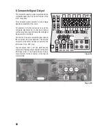
The composite signal converter outputs the formed
composite signal („SuS“) at the left contact of the
„ST2“ connection.
This composite signal consists of so many single
signals as measured at the inputs.
For example, if a 6-channel receiver is used, the
composite signal also has 6 channels. Channel
number recognition is performed via the valid signal
measurement at the inputs.
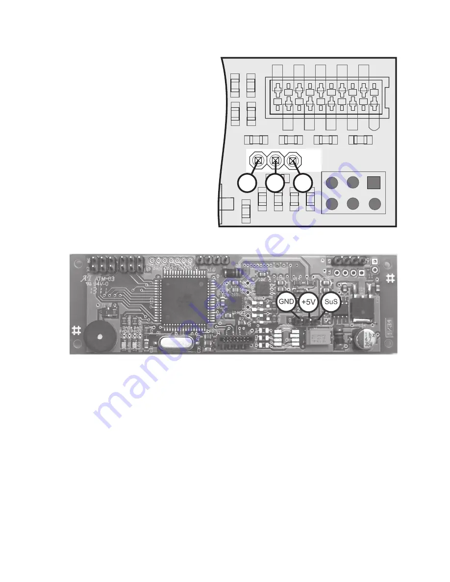
Connect the three-pole composite signal cable to
the connection „ST2“ (see figure 8a). The impulse
line (mark at the cable) must be connected to the
left contact of the „ST2“ plug.
The connections „SuS“, „+5V“ and „GND“ must be
connected to the respective connections of the main
PCB (figure 8b) in the QuadroCopter. Ensure
correct polarity for the connection of the two pin
contact strips!
C1
R9 R13
R10 R14
R3 R7 R11 R15
R4
R8
R12
R16
C6
ST3
ST1
1
2
5
6
ST2
+5V
GND
SuS
Figure 8b
Figure 8a
Summary of Contents for 450 ARF QC09
Page 166: ...166 ...
Page 167: ...167 ...

