background image


8540581 - 29/09/2010 - Rev.10 


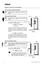
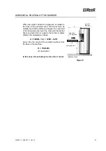
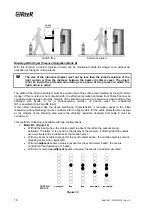
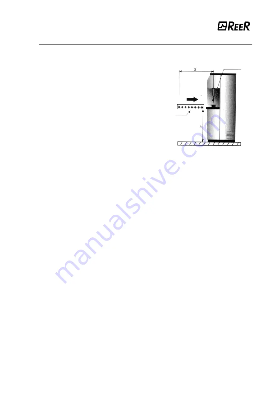
HORIZONTAL POSITION OF THE BARRIER  


When the object’s direction of approach is parallel to 
the floor of the protected area, the barrier must be 
installed so that the distance between the outer limit 
of the dangerous area and the most external optical 
beam is greater than or equal to the minimum safety 
distance 

S

 calculated as follows:  

S = 1600(t

1

 + t

2

) + 1200 – 0.4H 

where 

H

 is the height of the protected surface from 

the base of the machine; 

H = 15(D-50) 

(D=resolution) 


In this case, 

H

 must always be less than 1 meter. 
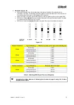


Figure 8 


safety barrier

point of 
danger

direction 
of approach 

reference plane 

Summary of Contents for ADMIRAL AX BK

Page 1: ...e Standard IEC 61508 1998 SILCL 3 according the Standard IEC 62061 2005 PL e according the Standard ISO 13849 1 2006 Electro sensitive Protective Equipments ESPE realizzati in conformit alle seguenti...

Page 2: ...CAL CONNECTIONS 10 EMITTER CONNECTIONS 11 RECEIVER CONNECTIONS 11 WARNINGS REGARDING THE CONNECTION CABLES 12 BLANKING FUNCTION 13 CONFIGURATION OF THE TYPE OF BLANKING 18 MULTIPLE SYSTEMS 25 USE OF D...

Page 3: ...d Receiver provides the necessary information for a correct use of the device and the evaluation of the possible operation defects ADMIRAL AX BK is ideal for the protection of Bending presses presses...

Page 4: ...rated by the barrier Figure 1 Figure 1 The resolution is constant irrespectively of work conditions as it only depends on the geometric characteristics of the lenses and the distance between the centr...

Page 5: ...h and height of the relative access area to be calculated Compare these dimensions with the maximum working range and the height of the protected area in relation to the specific model The general ins...

Page 6: ...e taken in order to prevent the formation of condensation on the lenses which could have an adverse effect on monitoring POSITION The position of the AXE BK Emitter and the AXR BK Receiver must preven...

Page 7: ...lled to detect the presence of a person between the vertical light curtain B and the dangerous machine at system power up or restart Figure 3 The length of the connection cable between the master and...

Page 8: ...h speed of object to the dangerous area mm sec t1 response time of the safety barrier in seconds sec t2 machine response time in seconds meaning the time required for the machine to interrupt the dang...

Page 9: ...t2 8 D 14 If due to the specific configuration of the machine the dangerous area can be accessed from above the highest beam of the barrier must be at a height H of at least 1800 mm from the base G of...

Page 10: ...een the outer limit of the dangerous area and the most external optical beam is greater than or equal to the minimum safety distance S calculated as follows S 1600 t1 t2 1200 0 4H where H is the heigh...

Page 11: ...l power supply must comply with the standard EN 60204 1 The electrical connections must be made according to the diagrams in this manual In particular do not connect other devices to the connectors of...

Page 12: ...ble 1 MASTER MODELS SECONDARY CONNECTOR M12 5 pin connector PIN COLOR NAME TYPE DESCRIPTION FUNCTIONING 1 Brown 24VDC 24 VDC power supply 3 Blue 0VDC 0 VDC power supply 5 Grey PE INPUT Ground connecti...

Page 13: ...NECTOR 8 poles M12 STANDARD MODELS 8 poles M12 connector PIN COLOR NAME TYPE DESCRIPTION FUNCTIONING 2 Brown 24VDC 24 VDC power supply 7 Blue 0VDC 0 VDC power supply 8 Red PE Ground connection 1 White...

Page 14: ...m of 3 adjacent beams with two different types of functioning according to the selected method of configuration The blanking function is useful in applications in which in specific safety conditions o...

Page 15: ...l the beams free the protected area is free With one beam occupied except for the synchronism beam the area is considered free With two or more beams occupied the area is considered occupied CURTAIN f...

Page 16: ...A3 50 mm 30 No blanking 40 mm 0 Floating blanking A1 70 mm 30 Floating blanking A2 100 mm 60 40 mm Floating blanking A3 130 mm 90 Nominal resolution Type of Blanking Distance between beams Maximum siz...

Page 17: ...ber of beams must be considered B1 is equivalent to A2 and B2 to A3 If the object introduced has the above mentioned characteristics a resolution equal to the initial resolution without blanking can b...

Page 18: ...pied the area is considered occupied CURTAIN occupied free free occupied free occupied STATUS Figure 15 Nominal resolution Type of Blanking Effective resolution at the edges of the blanking area No bl...

Page 19: ...pin 6 connected to 0VDC SEL_C pin 4 connected to 24VDC Blanking Without Object Presence Obligation Mode A2 SEL_A pin 5 connected to 24VDC SEL_B pin 6 connected to 24VDC SEL_C pin 4 connected to 0VDC...

Page 20: ...rating mode with Blanking Without Object Presence Obligation Mode A1 Figure 16 In order to assure a correct barrier operation it is necessary to connect the pins 2 and 4 of the Emitter according to ta...

Page 21: ...rating mode with Blanking Without Object Presence Obligation Mode A2 Figure 17 In order to assure a correct barrier operation it is necessary to connect the pins 2 and 4 of the Emitter according to ta...

Page 22: ...rating mode with Blanking Without Object Presence Obligation Mode A3 Figure 18 In order to assure a correct barrier operation it is necessary to connect the pins 2 and 4 of the Emitter according to ta...

Page 23: ...perating mode with Blanking With Object Presence Obligation Mode B1 Figure 19 In order to assure a correct barrier operation it is necessary to connect the pins 2 and 4 of the Emitter according to tab...

Page 24: ...perating mode with Blanking With Object Presence Obligation Mode B2 Figure 20 In order to assure a correct barrier operation it is necessary to connect the pins 2 and 4 of the Emitter according to tab...

Page 25: ...re 21 Example of connection in AUTOMATIC operating mode with Blanking With Object Presence Obligation Mode B1 Figure 22 In order to assure a correct barrier operation it is necessary to connect the pi...

Page 26: ...elative Receiver Figure 23 illustrates some examples of correct positioning when two photoelectric systems are installed Incorrect positioning could generate interference and may result in malfunction...

Page 27: ...a U shaped protection Figure 24 The following rules should be taken into consideration when using deviation mirrors Place the mirrors so as to ensure compliance with the minimum safety distance S Figu...

Page 28: ...ing surfaces and the protected area The minimum distance d must be calculated according to the distance l between the Emitter and the Receiver considering that the angle of projection and reception is...

Page 29: ...dering code 1330974 Figure 27 Position the optical axis of the first and last beam of the Emitter on the same axis as that of the corresponding beams on the Receiver Move the Emitter in order to find...

Page 30: ...nding on the system operation phase The tables below shows the different signals ref Figure 28 EMITTER RECEIVER Figure 28 EMITTER SIGNALS Normal operation FIXED SYMBOLS 7 SEGMENTS DISPLAY LED SYMBOL M...

Page 31: ...tion F no blanking OFF ON OFF None GUARD condition F no blanking with weak signal OFF ON ON BLANKING condition active OFF ON OFF BLANKING condition active with weak signal OFF ON ON Receiver initializ...

Page 32: ...Please see table 3 page 11 for details about the use of the test function The minimum duration of the TEST function must be 40 msec OUTPUT STATUS The ADMIRAL features two static PNP outputs on the Re...

Page 33: ...er AXM Admiral Slave AXS 14 mm Resolution Models 151 301 451 601 751 901 1051 1201 1351 1501 1651 1801 Number of beams 15 30 45 60 75 90 105 120 135 150 165 180 Response time AX 6 7 5 9 5 11 5 13 5 15...

Page 34: ...tion Models 609 759 909 1059 1209 1359 1509 1659 1809 Number of beams 9 11 13 15 17 19 21 23 25 Response time 6 6 6 6 6 6 6 5 7 7 Overall barrier ht mm 711 861 1011 1161 1311 1461 1611 1761 1911 PFHd...

Page 35: ...rsa first in the centre and then in the vicinity of both the Emitter and the Receiver Multibeam models Intercept each beam with an opaque object first in the center of the detection zone and then clos...

Page 36: ...surfaces It is therefore fundamental to pay particular attention during the cleaning phases of the curtain front window especially in environments where abrasive dusts are present E g cement factories...

Page 37: ...selection incorrect or modified ON OFF OFF Carefully check the connection of terminals 2 and 4 EXT_RANGE0 1 on the connector Internal error add on board ON OFF OFF Internal error master board ON OFF O...

Page 38: ...of the OSSD static outputs ON OFF OFF Carefully check the connection of terminals 1 and 3 OSSD on the connector OSSD static outputs error ON OFF OFF Take action in one of the following ways STANDARD a...

Page 39: ...the supply voltage levels comply with those specified in the technical data sheet the barrier power supply should be kept separate from that of the other electric power equipment electric motors inve...

Page 40: ...90 8 pin M12 female connector 5 m cable 1330983 C8D910 90 8 pin M12 female connector 10 m cable 1330984 C8D915 90 8 pin M12 female connector 15 m cable 1330985 C8DM9 Straight 8 pin M12 female connect...

Page 41: ...el not authorised by REER tampering etc Accidents or collisions also during transportation or due to acts of God Other reasons for which REER cannot be held responsible Repairs will be carried out at...

Reviews: