10
Distance from reflecting surfaces.
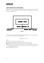
Reflecting surfaces located next to the photocell(s) may cause spurious reflections that would
close the optical path between the emitter and the receiver and inhibit the system's detection
capability (fig. 5).
Figure
Figure 5
5
Having completed the installation, check for the presence of reflecting surfaces which might
intercept the beam, first in the centre and then in the proximity of the emitter and the
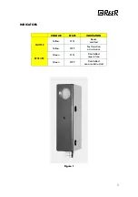
receiver. If any object is intercepted, the green led located on the receiver (fig. 1) must
never light up.
Multiple systems.
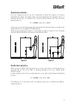
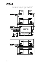
When using 2, 3 or 4 pairs of ULISSE UNC photocells arranged next to or on top of each
other in order to prevent them from mutually interfering it is necessary to arrange the
elements so that the beam emitted by one system is received only by the respective
receiver (fig. 6).
F
The emitter of one pair must not result in front of the receiver of the other pairs.
The emitter of one pair must not result in front of the receiver of the other pairs.
Figure
Figure 6
6
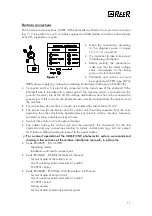
Systems arranged side by side: (A)
Systems arranged side by side: (A)
The two emitters are adjacent.
Systems one on top of the other: (B)
Systems one on top of the other: (B)
Emitters and receivers in cross position.

