11
Electrical connections
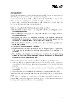
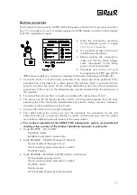
For the electrical connections, ULISSE UNC photocells are fitted with a 3 pin male connector
(fig. 7). It is possible to use 5 m cables equipped with M8 female connector, either straight
or at 90°, supplied on request.
•
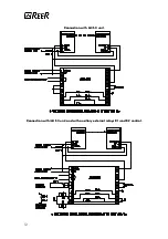
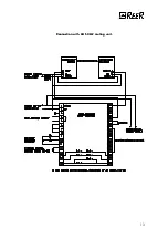
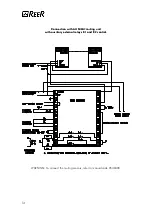
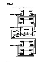
Make the connections according
to the diagrams given in pages
12, 13, 14, 15 and 16.
•
It is important to take into account
the following indications:
•
Before making the connections,
make sure that the mains voltage
value corresponds to the rating
given in the technical data.
•
Photocells and control unit must
be supplied with PELV type 24Vdc
±
20% power supply (e.g. through an isolating transformer conforming to EN 60742).
•
Connector pin No. 3 is electrically connected to the metal case of the photocell. If the
photocell has to be linked to a metal part of the machine which is connected to the
ground, the return line of the 24 Vdc voltage distribution system has to be connected to
ground too. If this is not so, the photocell case must be insulated from the metal part of
the machine.
•
For connections of over 50m in length, use cables with cross section of 1mm
2
.
•
The power line for the barrier and the control unit should be separate from the lines
powering the other electrically operated devices (electric motors, inverters, frequency
variators) or other possible sources of noise.
•
Connect the control unit to the ground socket.
•
The cables linking the control unit and the photocell, the connection for the test
command and any connections relating to system control parts (e.g. self-test output)
must follow a different path with respect to the power cables.
F
For a correct operation of the ULISSE UNC photoelectric system, we recommend
For a correct operation of the ULISSE UNC photoelectric system, we recommend
reading a few sections of the relative installation manuals; in particular:
reading a few sections of the relative installation manuals; in particular:
•
Code 8540399 - "AU S-TWIN":
–
Operating modes
–
Installation and electric connections
•
Code 8540404 - "ARGOLUX series AS" Manual:
–
Technical data of the output circuit
–
Use of auxiliary contact elements K1 and K2
–
The TEST control
•
Code 8540408 - "MUTING, AU S3M2 safety unit" Manual:
–
Technical data of output circuit
–
Use of auxiliary contact elements K1 and K2
–
The TEST control
–
Muting sensors
–
Technical data of external indicator system
Figure
Figure 7
7

