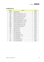
VISION VXL
8540615 • 19/12/2014 • Rev.8
25
TROUBLESHOOTING
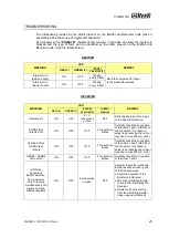
The indications provided by the LEDs present on the Emitter and Receiver units make it
possible to trace the cause of a system malfunction.
As indicated in the
“SIGNALS”
chapter of this
manual, in the case of a fault, the system is
blocked and the type of fault can be identified by the LEDs present on the Emitter and
Receiver units. (See the tables below).
EMITTER
MEANING
LED
REMEDY
RED (2)
GREEN (3)
(TEST)
YELLOW (1)
Internal error
(add-on board)
ON
OFF
blinking
every 2,5sec Send the equipment for repair
to the ReeR laboratories.
Internal error
(master board)
ON
OFF
blinking
every 0,8sec
RECEIVER
MEANING
LED
REMEDY
RED (5)
GREEN (7)
(CLEAR)
YELLOW (4)
(OSSD)
RED (6)
Internal error
ON
OFF
2 / 3
consecutive
pulses
OFF
Send the equipment for repair
to the ReeR laboratories.
OSSD static
outputs error
ON
OFF
OFF
2 consecutive
pulses
Carefully check the connection
of terminals 1 and 3 (OSSD) on
the connector. If necessary,
adjust load reducing the current
required to max 500 mA (2
F)
Overload of the
OSSD static
outputs
ON
OFF
OFF
3 consecutive
pulses
Carefully check the connection
of terminals 1 and 3 (OSSD) on
the connector. If necessary,
adjust load reducing the current
required to max 500 mA (2
F)
OSSD1 - OSSD2
short-circuit
ON
OFF
OFF
4 consecutive
pulses
Carefully check the connection
of terminals 1 and 3
Interfering
dangerous
Emitter detected.
The receiver is
able to receive
simultaneously the
beams from two
different Emitters
ON
OFF
6 consecutive
pulses
OFF
Carefully locate the interfering
Emitter and take action in one
of the following ways:
Switch the position of the
Emitter and Receiver.
Move the interfering Emitter
to avoid this illuminating the
Receiver.
Shield the beams coming
from the interfering Emitter
using opaque protections.

