VISION VXL
8540615 • 19/12/2014 • Rev.8
9
ELECTRICAL CONNECTIONS
WARNINGS
Before making the electrical connections, make sure that the supply voltage complies with
that specified in the technical data sheet.
Emitter and Receiver units must be supplied with 24Vdc±20% power supply that
guarantee safe isolation from main voltage.
The external power supply must comply with the standard EN 60204-1 (Chapter 6.4).
The electrical connections must be made according to the diagrams in this manual. In
particular, do not connect other devices to the connectors of the Emitter and Receiver.
For reliability of operation, when a diode jumper supply unit is used, its output capacity must
be at least 2000µF for each absorbed A.
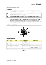
EMITTER CONNECTIONS
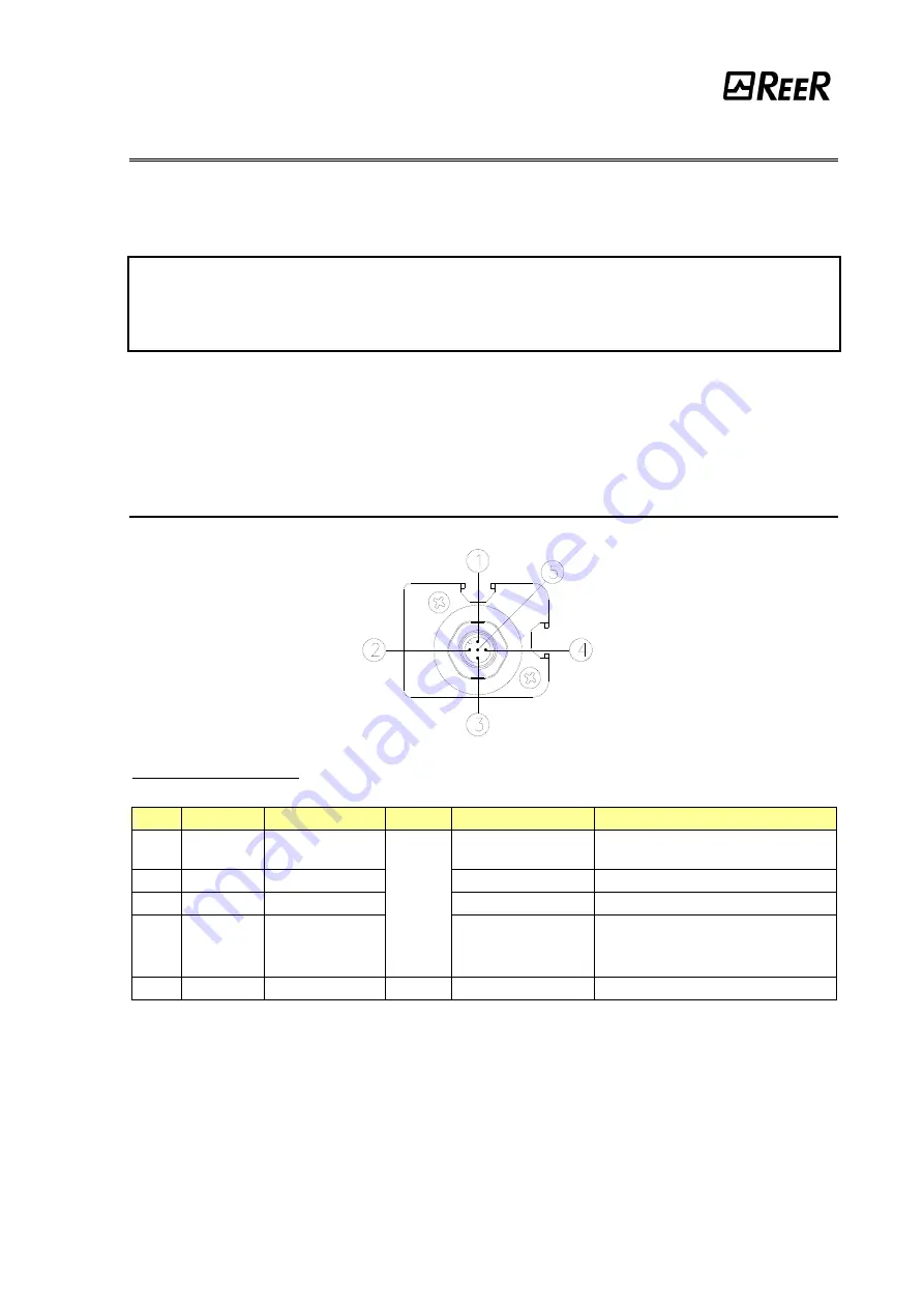
5 poles M12 connector
PIN
COLOR
NAME
TYPE
DESCRIPTION
FUNCTIONING
1
Brown
24VDC
INPUT
+24VDC power
supply
-
3
Blue
0VDC
0VDC power supply
-
5
Grey
FE
Ground connection
-
2
White
TEST
TEST request
- Operation without TEST (+24VDC)
- TEST request (Transition
+24VDC -> 0VDC or open circuit)
4
Black
N.C.
-
N.C.
-
Table 1


