VISION VXL
8540615 • 19/12/2014 • Rev.8
17
MECHANICAL ASSEMBLY AND OPTICAL ALIGNMENT
The Emitter and the Receiver must be assembled opposite each other (at a distance
specified in the technical data sheet). Use the
fastening brackets and inserts
supplied with
the system to place the Emitter and the Receiver so that these are aligned and parallel to
each other and with the connectors facing the same way.
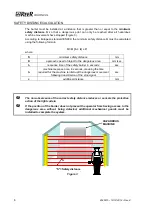
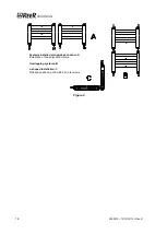
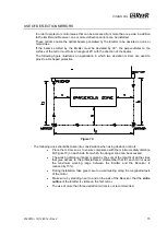
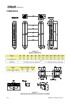
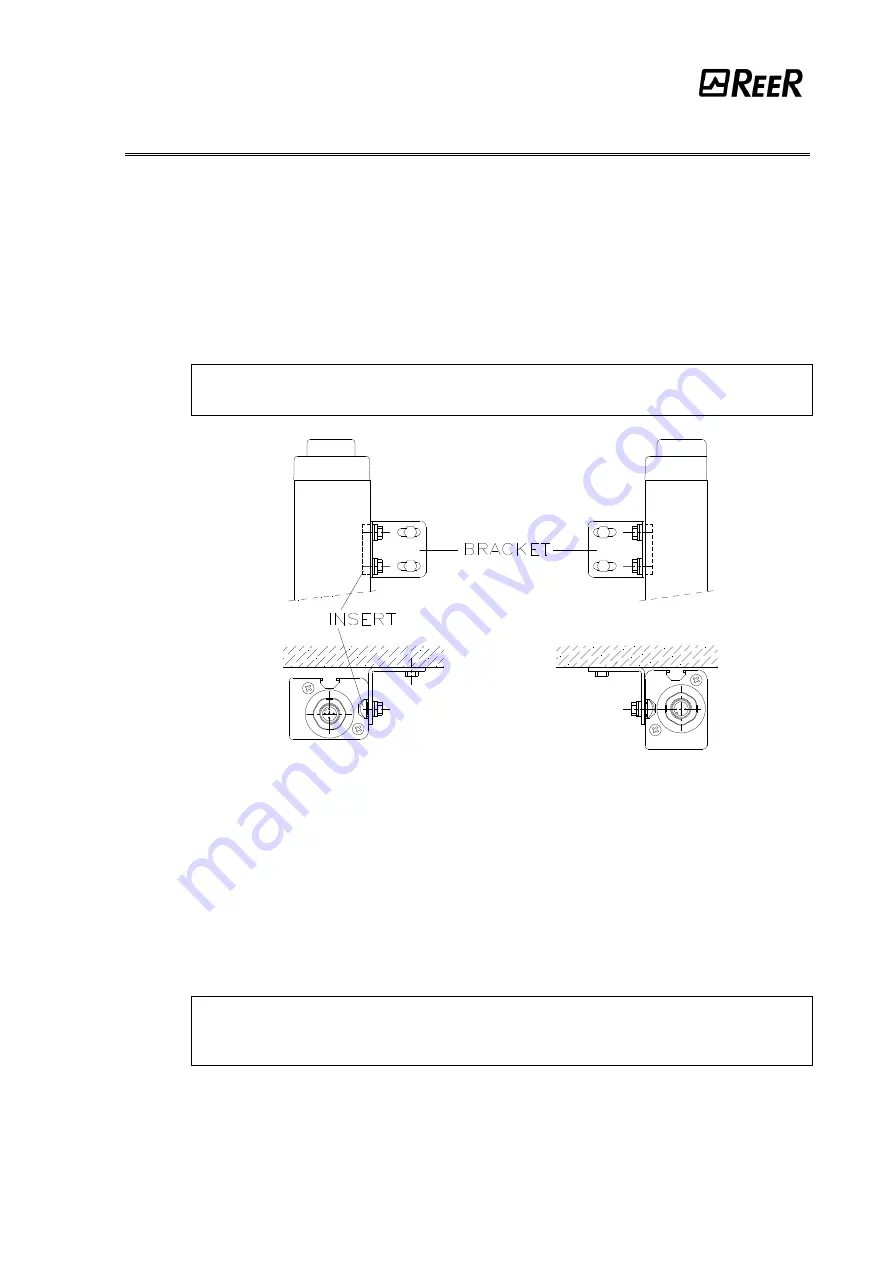
Depending on the dimensions and the shape of the support on which they are to be installed,
the Emitter and Receiver must be assembled with the fastening inserts at the back, or else
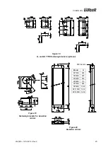
by fitting these in the side groove (Figure 13).
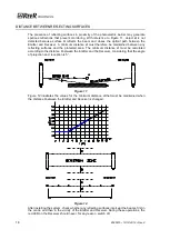
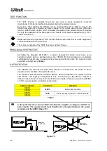
Perfect alignment of the Emitter and Receiver is essential in order to assure correct barrier
operation. The indicator LEDs on the Emitter and Receiver facilitate this operation.
To perform an easier alignment the use of SFB circular brackets is necessary.
These are available on request (ordering code 1330974).
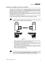
Figure 13
Position the optical axis of the first and last beam of the Emitter on the same
axis as that of the corresponding beams on the Receiver.
Move the Emitter in order to find the area within which the green LED on the
Receiver stays on, then position the first beam of the Emitter (the one close to
the indicator LEDs) in the centre of this area.
Using this beam as a pivot, effect small sideways movements of the opposite
end to move to the protected area clear condition. The green LED on the
Receiver will indicate this condition.
Lock the Emitter and Receiver in place.
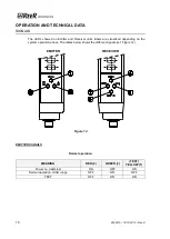
If the Emitter and the Receiver are assembled in areas that are subject to strong
vibrations,
the use of vibration-damping supports is necessary,
in order to
prevent circuit malfunctions (code SAV-3 1200088, code SAV-4 1200089).

