background image


TROUBLESHOOTING 

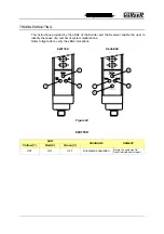
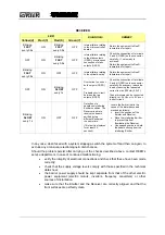
The instructions provided by the LEDs of the Emitter and the Receiver enable the user to 
identify the cause of a number of system malfunctions.  

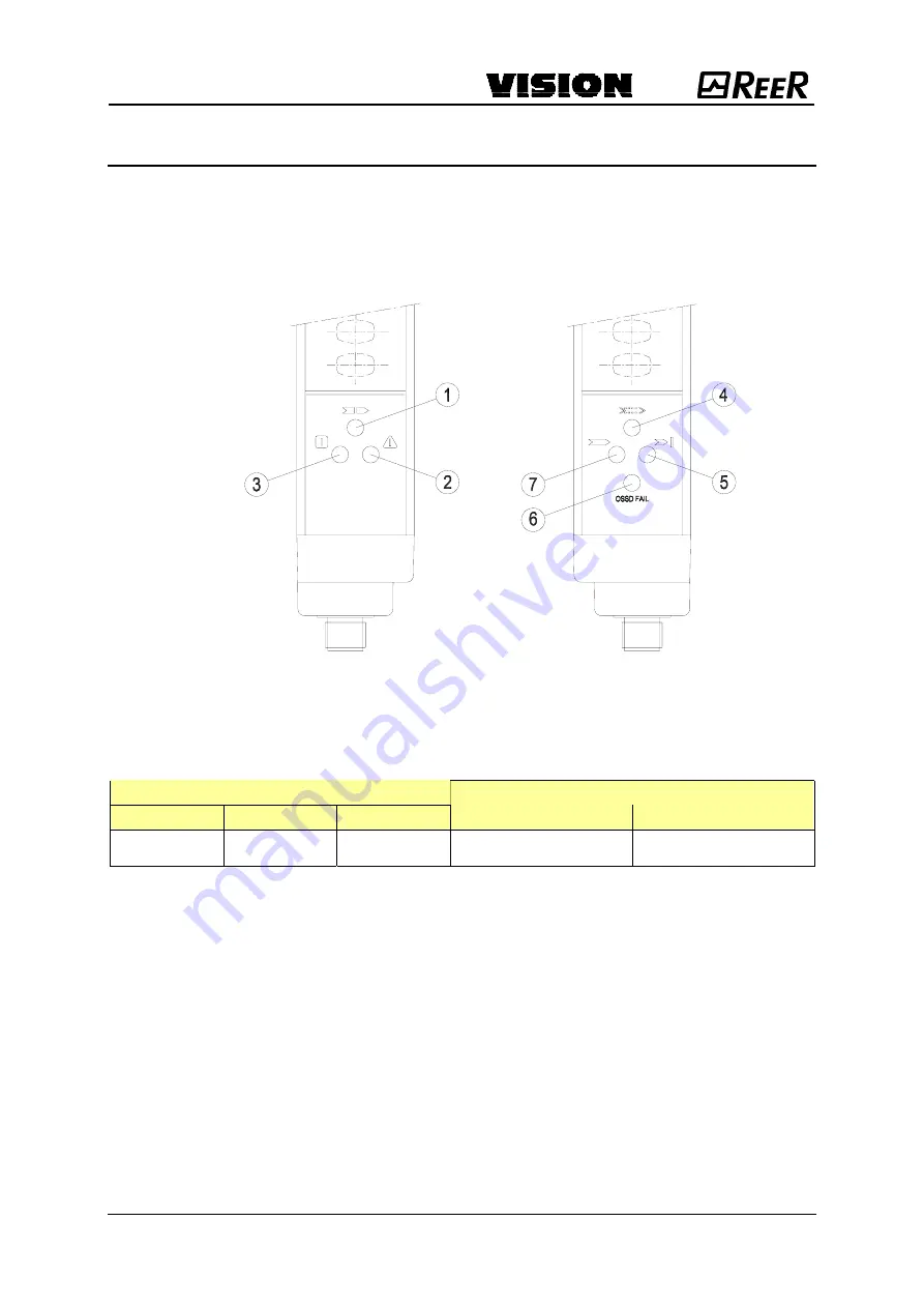
Refer to figure 24 to verify the LEDs indications. 


Figure 24 


EMITTER


LED 

Yellow (1) 

Red (2) 

Green (3) 

DIAGNOSIS 

REMEDY 

OFF ON OFF 

Anomalous operation 


Return the equipment to 
ReeR laboratories for repair.


EMITTER    RECEIVER 

Summary of Contents for VISION

Page 1: ...Acceso 5 Rosso Acceso 6 Rosso Acceso Accensione sistema 7 Verde Acceso Area protetta libera 5 Rosso Acceso Area protetta occupata Ricevitore 4 Giallo Acceso Segnale ricevuto debole NOTA Per una descrizione delle segnalazioni in caso di FAIL consultare il paragrafo DIAGNOSI GUASTI del presente manuale pagina 23 Figura 16 Î Nei modelli Multibeam è presente sull emettitore un led rosso in corrisponde...

Page 2: ...lare la causa di un non corretto funzionamento del sistema Facendo riferimento alla figura 24 verificare le indicazioni fornite dai LED Figura 24 EMETTITORE LED Giallo 1 Rosso 2 Verde 3 DIAGNOSI RISOLUZIONE OFF ON OFF Anomalia di funzionamento Inviare l apparecchiatura in riparazione presso i laboratori REER ...

Page 3: ...e contemporaneamente i raggi emessi da due diversi Emettitori Ricercare attentamente l Emettitore disturbante ed intervenire in uno dei seguenti modi Scambiare la posizione di Emettitore e Ricevitore Spostare l Emettitore interferente per evitare che illumini il Ricevitore Schermare i raggi provenienti dall Emettitore interferente mediante protezioni opache In ogni caso a fronte di un blocco del s...

Page 4: ...laboratori REER completa di tutte le sue parti indicando con chiarezza codice numerico del prodotto campo P N rilevabile dall etichetta di prodotto numero di matricola campo S N rilevabile dall etichetta di prodotto data di acquisto periodo di funzionamento tipo di applicazione guasto riscontrato ACCESSORI MODELLO ARTICOLO CODICE ...

Page 5: ...ellow On 5 Red On 6 Red On System activated 7 Green On Protected area clear 5 Red On Protected area engaged Receiver 4 Yellow On Weak signal received NOTE For a description of the signalings in case of FAIL please refer to the TROUBLESHOOTING paragraph in this manual page 23 Figure 16 Î On the emitter of the multibeam models near each beam is present a red led which permits an easy detection of th...

Page 6: ... enable the user to identify the cause of a number of system malfunctions Refer to figure 24 to verify the LEDs indications Figure 24 EMITTER LED Yellow 1 Red 2 Green 3 DIAGNOSIS REMEDY OFF ON OFF Anomalous operation Return the equipment to ReeR laboratories for repair EMITTER RECEIVER ...

Page 7: ...ON OFF OFF Detection of a hazardous interfering Emitter condition The Receiver is able to receive the beams emitted by two different Emitters at the same time This fault is displayed for at least 30 seconds Locate the Emitter that is the cause of the disturbance and proceed as follows Invert the positions of the Emitter and Receiver Move the interfering Emitter to prevent this from illuminating th...

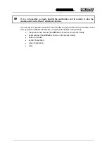
Page 8: ...cannot be restored after carrying out the above procedures send the equipment to REER s laboratories complete with all parts stating clearly the product code number the P N field is shown on the product label serial number the S N field is shown on the product label date of purchase period of operation type of application fault SPARE PARTS MODEL ARTICLE CODE ...

Reviews: