
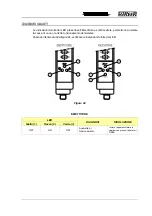

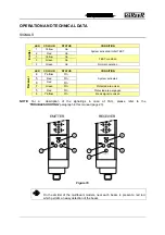
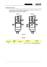
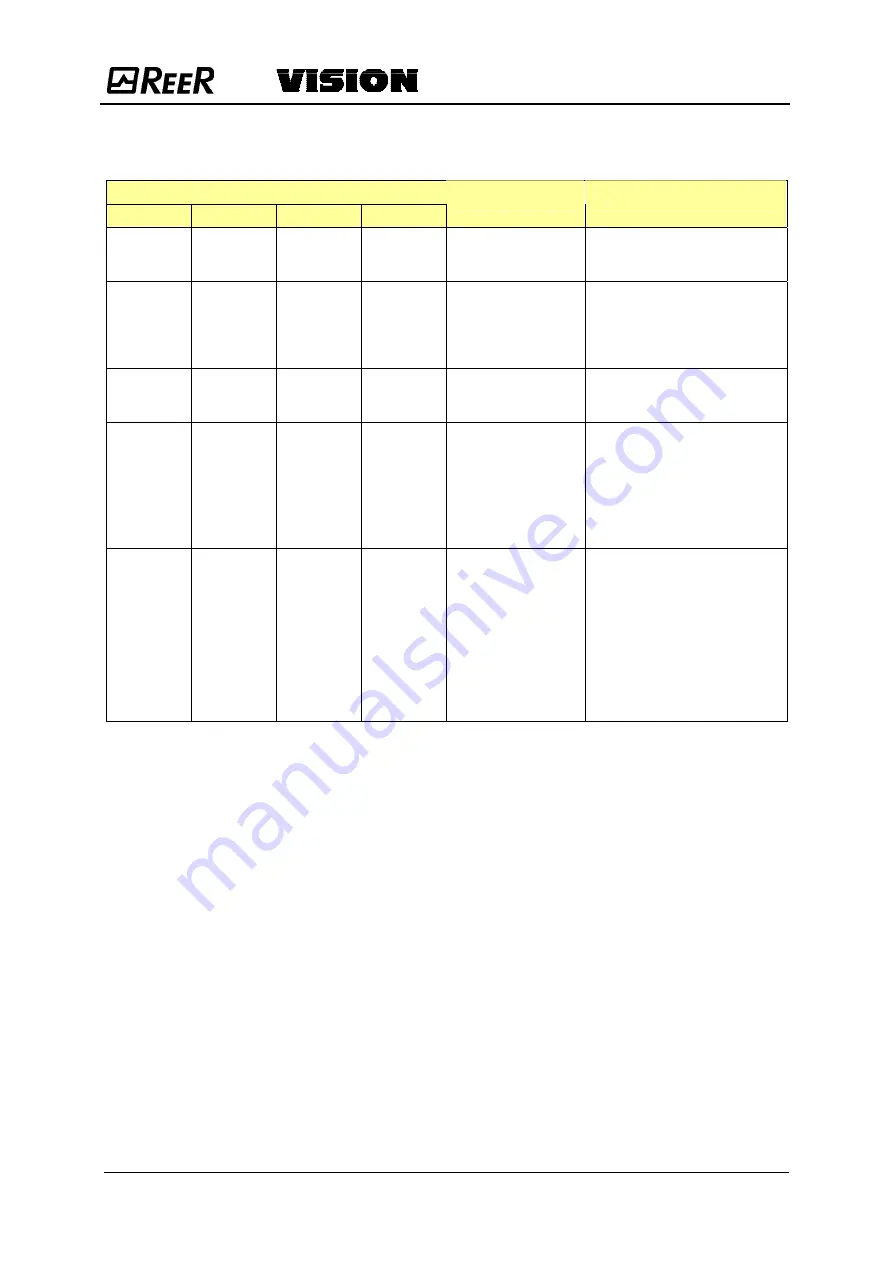
RECEIVER
LED
Yellow(4)
Red (5)
Red (6)
Green (7)
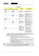
DIAGNOSIS
REMEDY
Blinking
FAST
every 0,5s
ON
Blinking
FAST
every 0,5s
OFF
Internal failure relating
to the microcontroller
boards
Return the equipment to ReeR
laboratories for repair.
OFF ON
Blinking
FAST
every 0,5s
OFF
Internal failure relating
to the static outputs
(OSSD), or erroneous
connection of static
outputs (OSSD).
Check the connection of terminals
2 and 4 (OSSD) on the connector
carefully. If no remedy is
achieved:
Return the equipment to ReeR
laboratories for repair.
Blinking
FAST
every 0,5s
ON OFF OFF
Internal failure relating
to the optical boards
Return the equipment to ReeR
laboratories for repair.
OFF ON
Blinking
SLOW
every 1s
OFF
Overcurrent on one or
both outputs (OSSD)
or
Probable short circuit
between the two
outputs (OSSD)
Check the connection of terminals
2 and 4 (OSSD) on the connector
carefully. If necessary, reduce the
load by reducing the requested
current to max. 500mA (2.2
µ
F).
These terminals can be connected
directly to + 24 Vdc or to 0 Vdc or
in short circuit.
Blinking
SLOW
every 1s
ON OFF OFF
Detection of a
hazardous interfering
Emitter condition. The
Receiver is able to
receive the beams
emitted by two
different Emitters at
the same time.
(This fault is displayed
for at least 30
seconds).
Locate the Emitter that is the
cause of the disturbance and
proceed as follows:
•
Invert the positions of the
Emitter and Receiver
•
Move the interfering Emitter
to prevent this from
illuminating the Receiver
•
Use opaque guards to shield
the beams coming from the
interfering Emitter
In any case, when faced with a system stoppage, switch the system off and then on again, to
exclude any occasional electromagnetic disturbances.
Should the problem persist after carrying out the checks described above, contact REER’s
service department. In case of continued malfunctioning:
•
verify the integrity of electrical connections and check that these have been made
correctly;
•
check that the supply voltage levels comply with those specified in the technical
data sheet;
•
the barrier power supply should be kept separate from that of the other electric
power equipment (electric motors, inverters, frequency converters) or other
sources of disturbance.
•
make sure that the Emitter and the Receiver are correctly aligned and that the
front surfaces are perfectly clean.


