User Manual
FROG-6
UM-0007-REV.06
Page 39
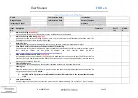
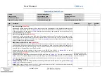
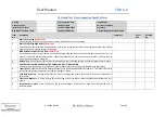
Visual Inspection Checklist Form
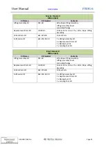
Unit No
This Inspection Date
Inspected by
Usage Category
Last Inspection Date
Position/ Company
Installation / Vessel
Signature
Avg No of Transfers / Year
Original Inspection record filed in
Item
No
Description
Comment
Pass /
Fail
Verified
By
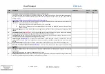
1.
Main Lift-Eye Plug
(Critical Part)
Visually inspect in situ for any signs of wear, cracks, deformation or other damage.
2.
Main Lift-Eye Plug M20 Bolts
(Critical Part)
Visually inspect the three M20 lifting eye bolts, nuts, split pins and tamper proof seals that connect the main Lift-
Eye plug to the central column for wear or damage.
3.
Back-Up Lift-Eye
Visually inspect for any wear or damage and check that the split pin and tamper proof seal are intact.
4.
Seat Base Assembly and the Hydraulic Damper and Anti-Tilt Assembly
Visually inspect for any wear
or damage and ensure that all bolts, clevis’ and other fasteners are fully secure. Ensure
that clevis pin threads are not visible on damper rods. (see Technical Bulletin 01-09 at
http://www.reflexmarine.com/index.cfm/p/Technical-Safety-Alerts
5.
M48 Keel Boss and M10 Cross Bolt
(Critical Part)
At the bottom end of central column, visually inspect the M48 keel boss nut and ensure that the M10 cross bolt is
secure c/w split pin and tamperproof seal. Check the presence of anti-rotation fittings and that all bolts are secure.
Do not go underneath an active lift.
6.
Frame and Buoyancy
Visually inspect for any damage and ensure that all bolts and fasteners are tight and fully secure.
7.
Landing Feet
Examine the feet to ensure that they are in good condition and that they are properly secured to the capsule. Do
not go underneath an active lift.
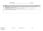
Notes:
i.
Measure height of foot and replace if under 120 mm in height
ii.
Small (20 mm in length) cuts are acceptable but feet should be replaced when the internal foam becomes
visible
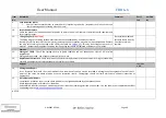
8.
Seat Harness Security
Visually inspect the seat harness attachment points and the harness webbing for any signs of wear, fraying or
damage. Check that attachment points are secure.
Summary of Contents for FROG-6 HC6-01 620
Page 62: ...User Manual FROG 6 UM 0007 REV 06 Page 62...
Page 63: ...User Manual FROG 6 UM 0007 REV 06 Page 63...
Page 64: ...User Manual FROG 6 UM 0007 REV 06 Page 64...
Page 65: ...User Manual FROG 6 UM 0007 REV 06 Page 65...
Page 66: ...User Manual FROG 6 UM 0007 REV 06 Page 66...
Page 67: ...User Manual FROG 6 UM 0007 REV 06 Page 67...
Page 68: ...User Manual FROG 6 UM 0007 REV 06 Page 68...
Page 69: ...User Manual FROG 6 UM 0007 REV 06 Page 69...
Page 70: ...User Manual FROG 6 UM 0007 REV 06 Page 70...
Page 71: ...User Manual FROG 6 UM 0007 REV 06 Page 71...
Page 72: ...User Manual FROG 6 UM 0007 REV 06 Page 72...
Page 73: ...User Manual FROG 6 UM 0007 REV 06 Page 73...
Page 74: ...User Manual FROG 6 UM 0007 REV 06 Page 74...
Page 75: ...User Manual FROG 6 UM 0007 REV 06 Page 75...
Page 76: ...User Manual FROG 6 UM 0007 REV 06 Page 76...
Page 77: ...User Manual FROG 6 UM 0007 REV 06 Page 77...
Page 78: ...User Manual FROG 6 UM 0007 REV 06 Page 78...
Page 81: ...User Manual FROG 6 UM 0007 REV 06 Page 81 12 2 Decals Vinyl Stickers Located on Buoyancy Units...
Page 82: ...User Manual FROG 6 UM 0007 REV 06 Page 82...
Page 83: ...User Manual FROG 6 UM 0007 REV 06 Page 83...
Page 84: ...User Manual FROG 6 UM 0007 REV 06 Page 84 12 3 Decal Operating Instructions Located on Seat...
Page 88: ...User Manual FROG 6 UM 0007 REV 06 Page 88 Link to Index Link to Index...
Page 93: ...User Manual FROG 6 UM 0007 REV 06 Page 93...
Page 94: ...User Manual FROG 6 UM 0007 REV 06 Page 94...
Page 95: ...User Manual FROG 6 UM 0007 REV 06 Page 95...

