background image

User Manual 


FROG-6 


               UM-0007-REV.06 


Page 58 


8.2.4


Inspection 

Before  and  after  transportation  the  FROG-6  must  be  inspected  to  check  for  damage  sustained  in 
transit.  The unit must not be used if any structural damage is observed.  If any damage has been 
observed please refer to 

Section 6.3

, item iv, for remedial instructions. 


8.2.5


Preparation for Road Transport 

Prior to shipping, the seat harnesses must be secured by tightening the seat harnesses and tying the 
buckles  together.  This  will  prevent  seat  harnesses  flapping  and  damaging  the  seating  area.  It  is 
recommended  that  the  FROG-6  is  covered  for  shipping  either  with  a  FROG-6  weatherproof 
protective cover or other heavy duty tarpaulin material. 
 

8.2.6


Crating and Shipping 

The FROG-6 will not fit in a standard or high-cube container. If the FROG-6 is transported on flat rack 
it must be secured. Recommended securing points  are the radial / peripheral floor braces and the 
back-up  eye.  To  protect  it  from  excess  loading,  the  main  Lift-Eye  must  not  be  used  as  a  securing 
point.  Feet  must  be  supported  to  prevent  collapse  by  placing  suitable  chocks  or  props  under  the 
unit. 
 

8.2.7


Storage 

The  FROG-6  has  been  designed  to  cope  with  the  harsh  conditions  on  an  offshore  installation  or 
vessel; however it is important to protect the unit as much as possible from any hazardous elements 
and UV degradation.  
 
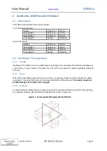
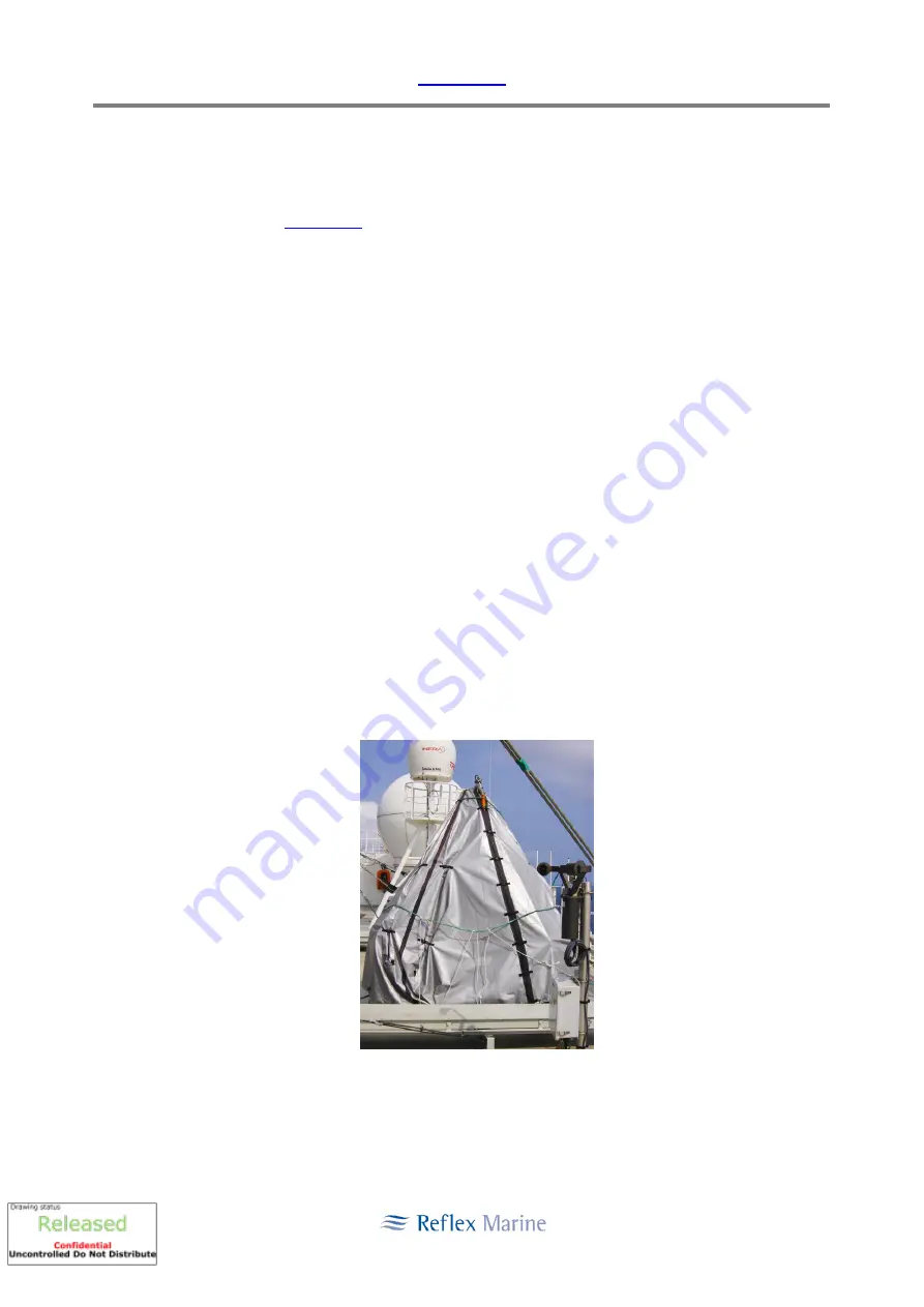
It  is  recommended  that  the  FROG-6  is  covered  with  the  FROG-6  weatherproof  cover  whilst  not  in 
use.  The cover fits the standard FROG-6 in both configurations. 


Fig 12: FROG-6 Protective Cover 


Link to Index


Summary of Contents for FROG-6 HC6-01 620

Page 1: ...FROG 6 User Manual Original Instructions for Frog Models HC6 01 620 Standard HC6 01 621 Mexico Standard HC6 01 622 Brazil Standard HC6 01 640 Arctic Rev 06 Issued 02 MAY 2019...

Page 2: ...g Reflex Marine Ltd or by downloading the latest manual revision from www reflexmarine com support Revision Approval Revision Date Issued Status Approved Name Signed 02 07 Jan 2008 Revised RML Operati...

Page 3: ...pdate Appendix E Update No Yes Yes No No 02 1 Section 6 Update to sections 6 2 6 3 and 6 6 Appendix C Update Appendix D Update No No No 03 The Frog 6 User Manual has been reformatted to be consistent...

Page 4: ...n 5 12 4 torque value updated Section 6 6 torque values updated Section 6 8 2 date format specified additions to available model numbers and note added regarding stamping of mass Section 6 10 1 detail...

Page 5: ...nual are issued to the following Reflex Marine Ltd Ref Status Issued To Date Issued Format Master Controlled RML Bristol P Onions 02 May 2019 Electronic Archived RML 1 Uncontrolled RML Truro M Trathen...

Page 6: ...Frog Transfer Operating Parameters 16 3 3 Operating Parameters Additional Factors 17 4 TRANSFER PLANNING 18 4 1 Risk Assessment and Method Statement 18 4 2 Communications 18 4 3 Information Exchange 1...

Page 7: ...sual Inspection 38 6 6 Examination 41 6 7 Post Load Test Visual Inspection 45 6 8 Proof Load Testing 48 6 8 1 Load Test Procedure 49 6 8 2 Inspection Data Plate 49 6 9 Sling Replacement and Management...

Page 8: ...ls Vinyl Stickers Located on Buoyancy Units 81 12 3 Decal Operating Instructions Located on Seat 84 13 APPENDIX E ACCESSORIES 85 14 APPENDIX F INDEPENDENT CERTIFICATION 86 14 1 EC Type examination cer...

Page 9: ...nels secondly a spring dampened seating assembly mounted on a central column All materials have been selected specifically to minimise corrosion in the marine environment The outer framework protects...

Page 10: ...ould be noted that some national regulations require cranes to be specifically certified for man riding operations v Supervisory personnel including Deck Crews and Crane Operators must be competent an...

Page 11: ...ture To ISO 9001 2008 Materials Frame SS 316 and A4 Stainless Steel Central Column Lift Eye Duplex SAF 2205 Lift Eye Connection Bolts Super Duplex UNS S32760 Other Steel Components SS 316 and A4 or A2...

Page 12: ...use in the Construction Industry Industry European Standards EC Machinery Directive EN 14121 1 EN292 Parts 1 2 Load Test ILO152 LOLER National Regulations UK PUWER LOLER Impact Behaviour The seating...

Page 13: ...Conformity and the User Manual will be translated into language of the country EC Member state in which the machinery is to be used This manual makes reference to CE marking of the FROG 6 however ther...

Page 14: ...olumn may deform on lateral impact and there may be damage to other components and therefore the equipment must be inspected after any impact Stability The unit has a low centre of gravity and a tripo...

Page 15: ...eed on a deck rising at full speed If there are concerns about heavy landings operators may wish to consider the following methods to reduce risk of heavy landings and take off dry runs without passen...

Page 16: ...the motion behaviour of the offshore installation the offshore crane and the supply vessel Further considerations may be given to the effects of shock absorbers motion compensators and lee side effect...

Page 17: ...ing FROG 6 for passenger embarkation Landing Area Clear of obstructions protrusions trip and fall hazards Landing Area Ice Spills Ice and spills must be cleaned from landing area prior to transfer Lan...

Page 18: ...vant 4 2 Communications Communications are an important part of controlling transfer operations Local communication practice will vary from work group to work group However dedicated 3 way radio commu...

Page 19: ...n It is recommended that video briefings are utilised for briefing transfer passengers supplemented as necessary by verbal briefing on any relevant installation vessel specific information 4 6 Supervi...

Page 20: ...tingency personnel transfers should not take place iii The crane boom should be fitted with adequate floodlights to illuminate the crane hook and FROG unit The Crane Operator must maintain a clear lin...

Page 21: ...r straps 5 Passengers Signal to deck crew when seat belt secure by holding hand up thumbs up 6 Deck Crew Ensure passengers are strapped in and hands and feet are correctly positioned 7 Deck Crew Ensur...

Page 22: ...entering the capsule It is also recommended that the Crane Operator slews the boom down weather from the capsule This will provide more time for the Crane Operator crews to react in the event of a fai...

Page 23: ...led correctly onto the shackle pin installed on the back up longer leg of the lifting assembly This part assembly is shown in Detail D of drawing 220 03 in Appendix B The shackle pin insert prevents t...

Page 24: ...d or caught on any adjacent equipment of structures iii Ensure tag lines are clear of knotting and deck crew have suitable hand and eye protection 5 6 Seating and Load Distribution In order to perform...

Page 25: ...ded for small light weight hand carry items such as laptops and operators should ensure that the payload does not exceed the maximum permitted weight see Note See Appendix G for Brazil unit 622 differ...

Page 26: ...ents ii The Deck Supervisor Banksman will shout OUT OUT OUT iii Personnel to release seat belt buckles and vacate FROG iv Deck Supervisor Banksman will direct passengers to a safe area Images sources...

Page 27: ...on Some items for consideration whilst establishing PPE are i Survival rates in water summer and winter ii Wind temperature ranges iii Proximity of overboard rescue facility fast rescue boat FRB stand...

Page 28: ...RML recommend that passengers are made aware of the specific risk of inflation during Strapping in Inherently buoyant yoke type lifejacket 100 150 N This type of PFD is bulky and may prove restrictiv...

Page 29: ...and donned 1 set for in transit for next uplift transfers Total PFD requirement for FROG 6 3 x 6 2 20 PFD s iii Deck crew should ensure that when passengers are exiting the FROG the passengers move cl...

Page 30: ...ace for realignment of the buoyancy units 6 Seated 1 seated stretcher Figure 7 Stretcher Mode Arrangement Tools Required i 8 mm Hex Key for M12 screws Buoyancy ii FROG 6 Diagrams 5 12 2 Stretcher Mode...

Page 31: ...e 9 Stretcher Fitting Diagram v Ensure the stretcher is firmly secure vi The casualty should be accompanied during the transfer procedure A maximum of two supporting passengers are recommended See sea...

Page 32: ...7 REV 06 Page 32 Specifications Length 2180 mm Width 1 610 mm Depth 190 mm Weight 10 kg Load Limit 275 kg Includes weight of patient stretcher and any medical equipment Operating Temperature 40 Deg C...

Page 33: ...n is formally recorded Examination An Examination is a careful and critical assessment of the components carried out by a Competent Person This should include dismantling the assembly and performing a...

Page 34: ...must always be carried out on schedule iv Where the FROG has sustained substantial damage a detailed examination of the unit must be carried out to ensure the integrity of the unit before conducting...

Page 35: ...reduced not exceeding not exceeding not exceeding Very Low 20 before every use 6 months 12 months After Load Test On Critical Parts Replacement 12 months 36 months 10 years Low 100 before every use 6...

Page 36: ...e recorded appropriately e g an entry in the daily tour record stating date the check has been completed unit number and any relevant comments What drawings are required to support this check The draw...

Page 37: ...Check KEEL NUT CROSS BOLT is in position with split pin and tamper proof seal 5 Check all Frog 6 FITTINGS FRAME and BUOYANCY are in good order 6 Check SEAT HARNESSES operate properly and attachment po...

Page 38: ...A ladder ii An inspection frame or floor matting iii Good lighting A suitable means of safely accessing the top and the bottom parts of the FROG 6 is required When using a step ladder or ladder it mu...

Page 39: ...fully secure Ensure that clevis pin threads are not visible on damper rods see Technical Bulletin 01 09 at http www reflexmarine com index cfm p Technical Safety Alerts 5 M48 Keel Boss and M10 Cross B...

Page 40: ...est date stamp specify decision to retain or replace Storage 12 Storage of FROG Check the storage cover is in good condition and not showing any signs of UV or wind degradation Storage off the ground...

Page 41: ...s examination i A ladder ii An inspection frame or floor matting iii Good lighting iv Appropriate metric tool kit socket set combination spanners allen keys etc v Riveter vi Inspection and test plate...

Page 42: ...Cross Bolt Critical Parts Remove the M48 keel boss nut and visually check that the threads at the bottom of the central column tube are in good condition Before replacing the keel nut ensure the thre...

Page 43: ...Visually inspect the seat harness attachment points and the harness webbing for any signs of wear fraying or damage Check that attachment points are secure 11 Seat Harnesses sit in Check all seat har...

Page 44: ...emplate As a minimum photos of each of the 16 points in the check list should be taken 18 Documentation Report Complete a report as recommended in the RML inspection template Reflex Marine Ltd offer t...

Page 45: ...is required to perform this inspection i A ladder ii An inspection frame or floor matting iii Good lighting A suitable means of safely accessing the top and the bottom parts of the FROG 6 is required...

Page 46: ...hat the M10 cross bolt is secure c w split pin and tamperproof seal Check the presence of anti rotation fittings and that all bolts are secure Do not go underneath an active lift 4 Backup Eye Visually...

Page 47: ...plate including the ready for dispatch after completion of the post load test inspection 11 Documentation Report Complete a report as recommended in the RML inspection template Reflex Marine Ltd offer...

Page 48: ...and certified test person Does this test require a formal record Yes What drawings are required to support this test The required drawings are available in Appendix B What equipment is required to pe...

Page 49: ...evenly Basis of Test Proof Load Twice Maximum Gross Weight less Tare Weight 2 x 1200 kg 630 kg 1770 kg Twice Maximum Gross Weight less Tare Weight 2 x 1200 kg 630 kg 1770 kg Crane Hook Load 2400 kg 2...

Page 50: ...sling sets vi Replace slings according to usage and inspection results vii Remove the velcro cover if a FROG unit or the sling set is to be removed from service for more than one month viii Store sli...

Page 51: ...typically HC6 XXX where XXX represents a three digit number Replace the critical parts as identified in the Examination Checklist according to the usage of the FROG see Table 3 in Section 6 3 This ma...

Page 52: ...ent Parts Kit 1 x Backup Eye Kit 1 x Landing Foot Kit Backup Eye Kit H BEK 01 1 x Backup Eye Bolt plus associated fixings Common Kits Kit Name Kit Number Contents Harness Kit H RHK 01 6 x Harnesses pl...

Page 53: ...t 621 FSK 01 30 1 x Lifting Assembly Kit 1 x Replacement Parts Kit 1 x Backup Eye Kit 1 x Landing Foot Kit Brazil Standard FROG 6 622 Kit Name Kit Number Contents Lifting Assembly Kit 221 30 Wire Rope...

Page 54: ...gistics for small parts Reflex Marine Ltd would be pleased to offer the recommended minimum stock items for critical and replacement parts for your operation please contact support reflexmarine com 6...

Page 55: ...to the inspection data plate and a new load test certificate issued 5 Years 1 Remove lifting assembly 2 Place lifting assembly into dry storage 3 Ensure the unit is chocked up off its feet stored in a...

Page 56: ...a build serial number These serial numbers are allocated sequentially in the order in which FROG 6 units are built Serial numbers start from HC6 001 and continue in numerical sequence The serial numb...

Page 57: ...t truck may damage the underside of the FROG 6 landing feet cross braces or main column Therefore the unit must be secured to a pallet specifically designed for forks 8 2 2 Crane When lifting the FROG...

Page 58: ...uty tarpaulin material 8 2 6 Crating and Shipping The FROG 6 will not fit in a standard or high cube container If the FROG 6 is transported on flat rack it must be secured Recommended securing points...

Page 59: ...for prolonged periods of inactivity then the user should consider a set of chocks to lift the feet away from the deck Reflex can supply a dedicated set of supporting chocks that are designed to fit p...

Page 60: ...portant note to passengers Certain National regulations place constraints on the use of personnel transfers Passengers should ensure they are aware of any local regulations prior to proceeding Name De...

Page 61: ...Assembly 620 03 Sheets 1 2 C Frog 6 Central Column Assembly 620 04 C Frog 6 Load Path Assembly 620 07 Sheets 1 2 B Frog 6 Seat Assembly 220 30 D 30ft Lifting Assembly RP0277 A Frog 6 Torque Settings...

Page 62: ...User Manual FROG 6 UM 0007 REV 06 Page 62...

Page 63: ...User Manual FROG 6 UM 0007 REV 06 Page 63...

Page 64: ...User Manual FROG 6 UM 0007 REV 06 Page 64...

Page 65: ...User Manual FROG 6 UM 0007 REV 06 Page 65...

Page 66: ...User Manual FROG 6 UM 0007 REV 06 Page 66...

Page 67: ...User Manual FROG 6 UM 0007 REV 06 Page 67...

Page 68: ...User Manual FROG 6 UM 0007 REV 06 Page 68...

Page 69: ...User Manual FROG 6 UM 0007 REV 06 Page 69...

Page 70: ...User Manual FROG 6 UM 0007 REV 06 Page 70...

Page 71: ...User Manual FROG 6 UM 0007 REV 06 Page 71...

Page 72: ...User Manual FROG 6 UM 0007 REV 06 Page 72...

Page 73: ...User Manual FROG 6 UM 0007 REV 06 Page 73...

Page 74: ...User Manual FROG 6 UM 0007 REV 06 Page 74...

Page 75: ...User Manual FROG 6 UM 0007 REV 06 Page 75...

Page 76: ...User Manual FROG 6 UM 0007 REV 06 Page 76...

Page 77: ...User Manual FROG 6 UM 0007 REV 06 Page 77...

Page 78: ...User Manual FROG 6 UM 0007 REV 06 Page 78...

Page 79: ...onents are those in which if failure were to occur there would be a high risk to the safety of the passengers in the FROG 6 The critical components are all connected to the Main Support Tube which is...

Page 80: ...d with the following information i Description of Equipment ii Model iii Build Version iv Serial Number v Manufacturer s Address vi Year of Construction vii Mass of Usual Configuration Mass without Pa...

Page 81: ...User Manual FROG 6 UM 0007 REV 06 Page 81 12 2 Decals Vinyl Stickers Located on Buoyancy Units...

Page 82: ...User Manual FROG 6 UM 0007 REV 06 Page 82...

Page 83: ...User Manual FROG 6 UM 0007 REV 06 Page 83...

Page 84: ...User Manual FROG 6 UM 0007 REV 06 Page 84 12 3 Decal Operating Instructions Located on Seat...

Page 85: ...of FROG 6 Note The strobe is not certified for use in hazardous areas Stretcher Essential for conducting emergency medical transfers Reflex Marine supply rigid stretcher that are compliant to use in F...

Page 86: ...FROG 6 UM 0007 REV 06 Page 86 14 APPENDIX F INDEPENDENT CERTIFICATION 14 1 EC Type examination certificate unit numbers HC6 110 to 112 and HC6 118 onwards Link to Index Link to Index Link to Index Li...

Page 87: ...User Manual FROG 6 UM 0007 REV 06 Page 87 14 2 ABS Product Type Approval unit numbers HC6 110 to 112 and HC6 118 onwards Link to Index Link to Index...

Page 88: ...User Manual FROG 6 UM 0007 REV 06 Page 88 Link to Index Link to Index...

Page 89: ...User Manual FROG 6 UM 0007 REV 06 Page 89 14 3 Marina Mercante Merchant Marine Mexico approval certificate all units HC6 01 621...

Page 90: ...User Manual FROG 6 UM 0007 REV 06 Page 90 14 4 Diretoria de Portos e Costas DPC Brazil approval certificate all units HC6 01 622...

Page 91: ...b Tare Weight 630 kg 1389 lb 5 6 Seating and Load Distribution In order to perform loading efficiently and safely the following procedures are recommended i Organise passengers into groups of 6 see no...

Page 92: ...i Back Up Lift Eye ii Central Column Load Bearing Assembly iii iii Seats and Floor Structure Test Proof Load 1830 kg 4034 lb 1830 kg 4034 lb Test Proof Load Distribution 1180 kg 2601 lb on the seats a...

Page 93: ...User Manual FROG 6 UM 0007 REV 06 Page 93...

Page 94: ...User Manual FROG 6 UM 0007 REV 06 Page 94...

Page 95: ...User Manual FROG 6 UM 0007 REV 06 Page 95...

Page 96: ...User Manual FROG 6 UM 0007 REV 06 Page 96...

Page 97: ...User Manual FROG 6 UM 0007 REV 06 Page 97...

Reviews: